L322 Range Rover System Description and Operation

STEERING
DESCRIPTION AND OPERATION
57-3
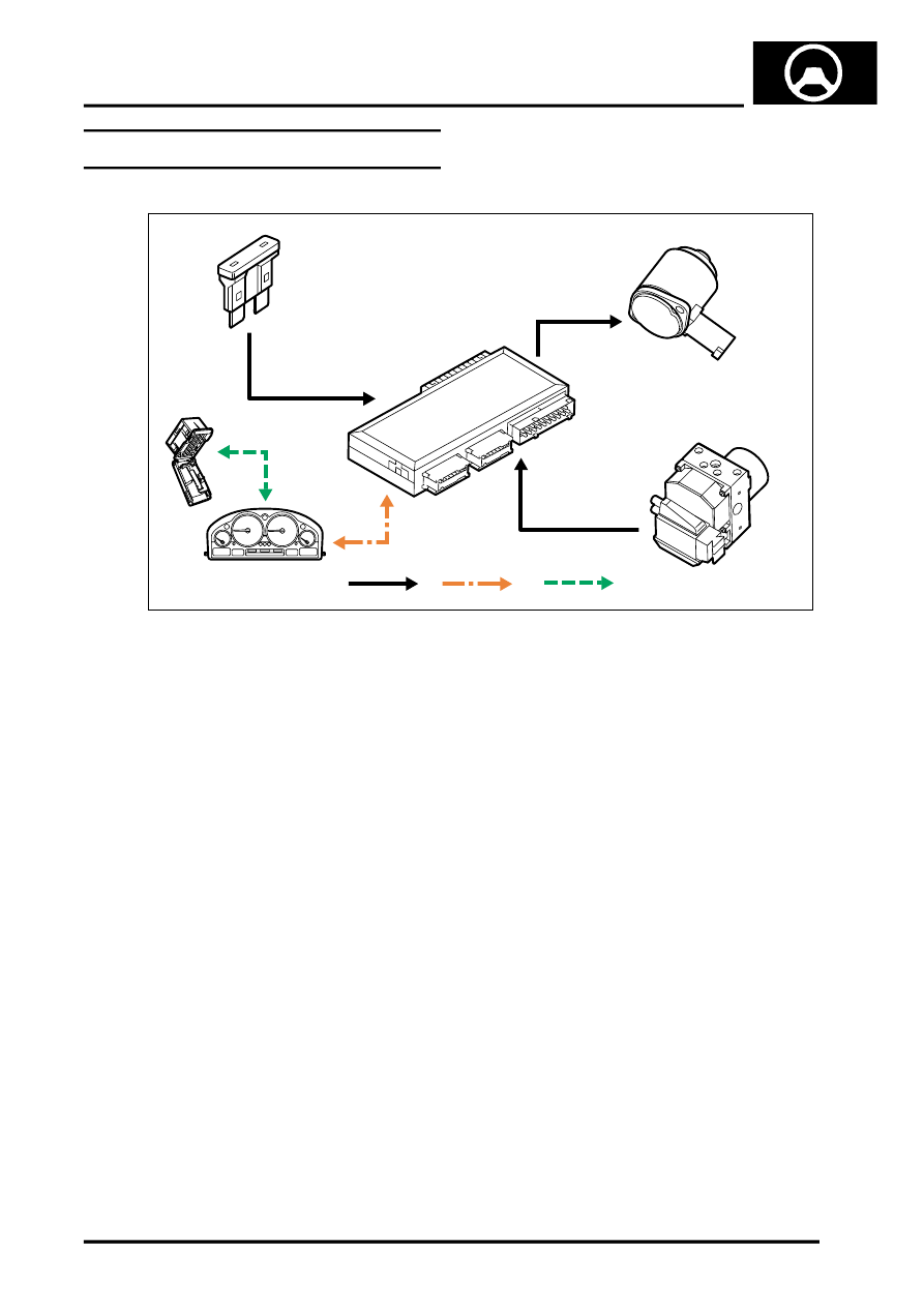
Steering Control Diagram – Servotronic
A = Hardwired; B = K Bus; C = Diagnostic DS2 bus
1 Fuse 5A – Battery permanent supply
2 Servotronic valve
3 Body Control Unit (BCU)
4 ABS ECU
5 Instrument pack
6 Diagnostic socket
M57 1179A
1
A
2
3
4
5
6
B
C
