L322 Range Rover System Description and Operation

SUSPENSION
60-12
DESCRIPTION AND OPERATION
The electric motor drives a crank with an eccentric pin to which a connecting rod is attached. The connecting rod has
a piston which fits in the bore of the compressor. Operation of the motor rotates the crank, moving the piston in the
bore of the compressor. The compressor is attached with special bolts to the motor housing and sealed with an O-
ring. The compressor has a temperature sensor located in its housing. The sensor measures the compressor
temperature which is measured by the air suspension ECU.
Attached to the compressor is the air dryer which contains a silicate box for removing moisture from the compressed
air. Air supplied to inflate the air springs passes through the air dryer. When the air springs are deflated, the exhaust
air also passes through the air dryer, removing the moisture from the unit.
Attached to the end of the air dryer unit is a solenoid operated exhaust pilot valve. This valve is opened when the air
springs are to be deflated.
Located in the same housing as the exhaust pilot valve is a pressure limiting valve which, on systems without an
external pressure relief valve, protects the air springs from over inflation. The valve is pneumatically operated,
responding to air pressure applied to it to overcome pressure from a spring located behind the valve. The pressure
limiting valve also operates when the exhaust pilot valve is opened, allowing air returning from the air springs to be
exhausted.
The compressor is used to supply air pressure to the air suspension reservoir. The ECU monitors the pressure within
the reservoir and, when the engine is running, maintains a pressure of:
l
13.7 bar (199 lbf/in
2
), in systems without an external pressure relief valve
l
11.8 bar (171 lbf/in
2
), in systems with an external pressure relief valve
There are a number of conditions that will inhibit operation of the air suspension compressor. It is vitally important that
these inhibits are not confused with a system malfunction. A full list of compressor inhibits is contained in the Air
Suspension Control section.
A temperature sensor is located within the compressor. If the compressor temperature rises above set limits, the ECU
will inhibit compressor operation.
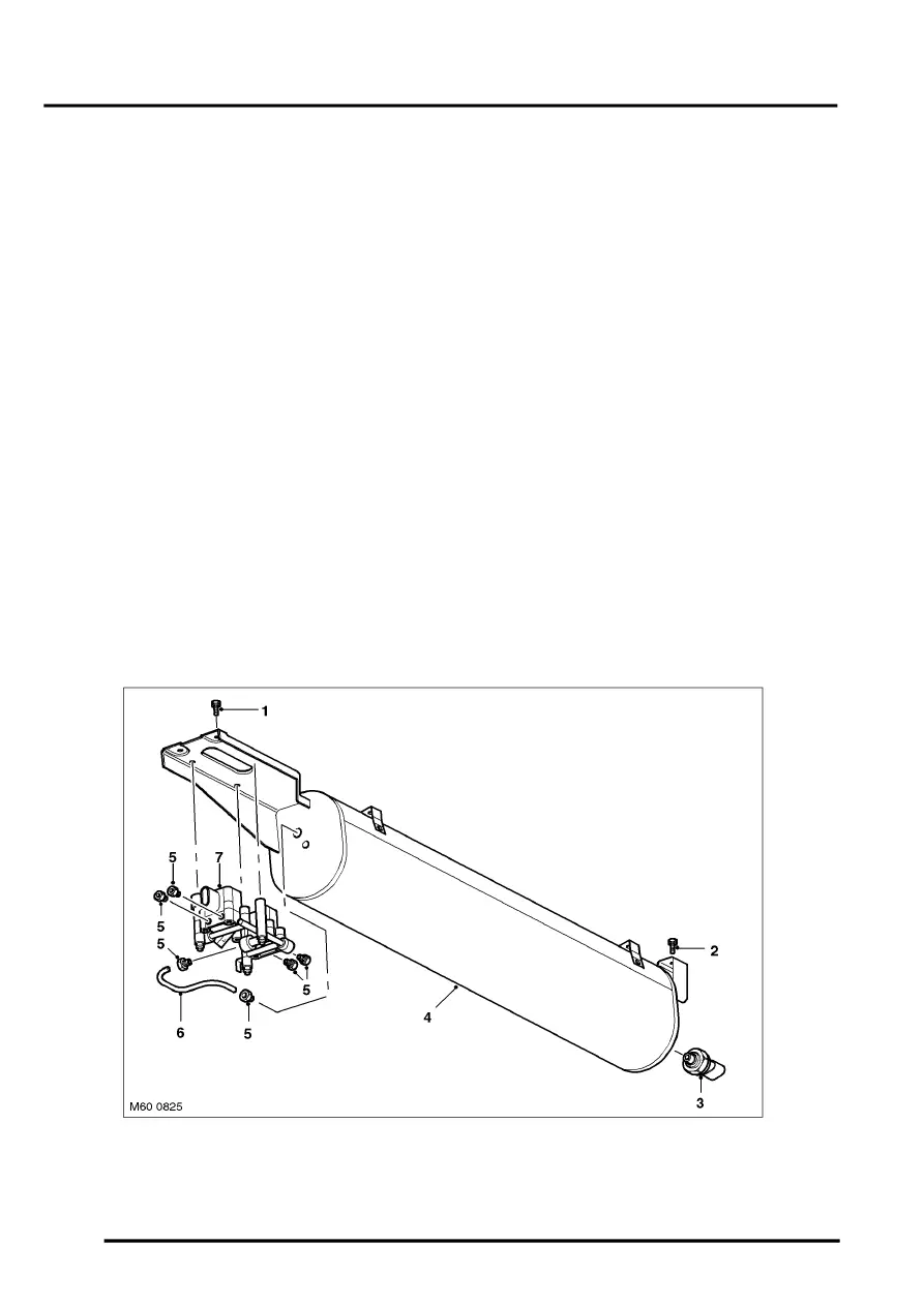
Reservoir
1 Reservoir mounting screw – front
2 Reservoir mounting screw – rear
3 Air pressure sensor
4 Reservoir
5 Air hose connectors
6 Hose – reservoir pressure to valve block
7 Valve block
