
L322 Range Rover System Description and Operation
SUSPENSION
60-4
DESCRIPTION AND OPERATION
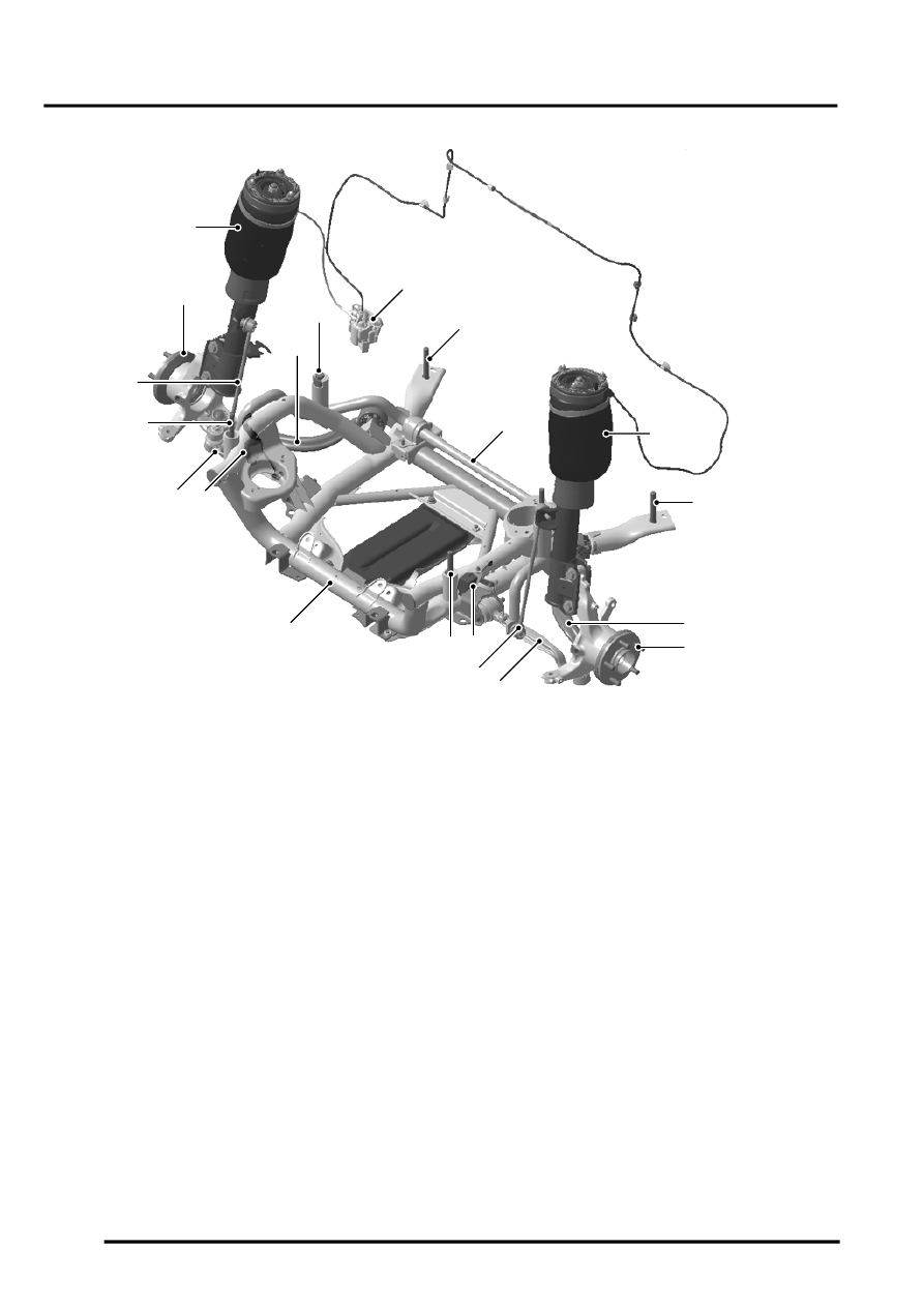
Front Suspension Components
1 RH front strut assembly
2 RH tie rod
3 Subframe body mounts
4 Front cross link valve
5 Anti-roll bar
6 LH front strut assembly
7 LH tie rod
8 LH front hub assembly
9 LH lower arm
10 LH anti-roll bar link
11 LH front height sensor
12 Front subframe
13 RH front height sensor (hidden)
14 RH lower arm
15 RH anti-roll bar link
16 RH front hub assembly
Struts
The front suspension struts are a MacPherson twin tube design with the conventional coil spring replaced by an air
spring. The lower end of the strut is connected to the front hub assembly with two bolts. The upper top mount is
attached to the inner wing with three studs and nuts.
The top mount has a bearing installed which reduces the force required on the steering when the strut rotates. A paper
gasket is fitted on the underside of the inner wing, between the inner wing and the top mount. The gasket prevents
the ingress of dirt and moisture into the bearing. When the strut is removed, this gasket must be replaced with a new
item to maintain the performance of the bearing and care must be taken to ensure that the gasket is correctly
positioned.
The damper functions by restricting the flow of hydraulic fluid through internal galleries within the damper. A damper
rod moves axially within the damper. As the rod moves, its movement is limited by the flow of fluid through the galleries
thus providing damping of undulations in the terrain. The damper rod is sealed at its exit point from the damper body
to maintain fluid within the unit and to prevent the ingress of dirt and moisture. The seal also acts as a wiper to keep
the rod outer diameter clean.
M60 0821
1
4
3
5
6
3
8
9
10
11
3
12
13
14
16
15
3
2
3
7