
L322 Range Rover System Description and Operation
TRANSFER BOX
DESCRIPTION AND OPERATION
41-17
The side gears have helical teeth machined on their outer circumference. The inner diameter of the side gears are
different sizes and both have machined splines. The side gear with the smaller diameter bore locates on mating
splines on the main shaft and provides output drive to the rear propeller shaft. The remaining side gear locates on
mating splines on the drive sprocket and, via the chain and the front output shaft, provides output drive to the front
propeller shaft. The side gears are located in the housing, supported laterally by the pinion gears. Transverse location
is provided by the main shaft and three pairs of friction washers.
The friction washers comprise one washer with two ground faces. The second washer has one ground face and the
opposite face has a sintered friction material. Axial thrust applied to the side gears from the pinion gears, forces the
side gears into contact with two of the three pairs of thrust washers, causing a locking of the side and pinion gears
under certain circumstances.
The cover plate is located on the open end of the housing and is secured with three bolts. The cover plate provides
location for the ends of the pinion gears. A cast recess for each pinion gear retains oil to lubricate the pinion gear ends.
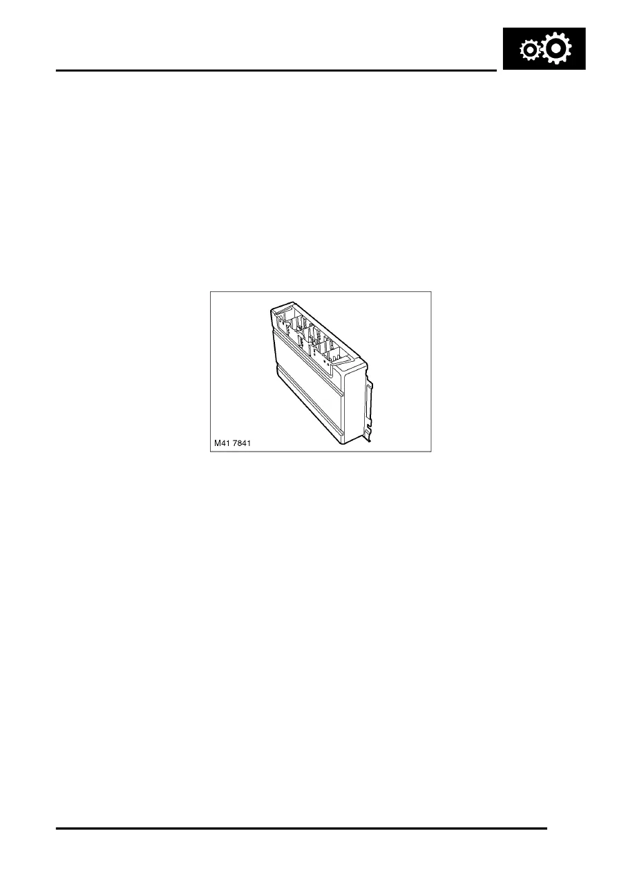
Transfer Box ECU
The transfer box ECU is located behind the battery, on the bulkhead. The position of the ECU changes with LH and
RH drive vehicles.
The transfer box ECU is the main unit for controlling the operation of the transfer box. The ECU software was designed
in conjunction with Land Rover, Siemens and New Venture Gear. The ECU is connected on the CAN bus and controls
the transfer box operation using CAN messages from other ECU's on the network.
The transfer box ECU uses three connectors for all inputs and outputs. The ECU receives one permanent power
supply via a 50A fusible link located on the bulkhead, behind the battery, and an ignition supply via fuse 33 in the
passenger compartment fusebox. A second feed via the ignition switch position I and fuse 37 in the passenger
compartment fusebox, activates the neutral selection function. Refer to Operation - Neutral Selection for further
details.
The ECU memorises the position of the actuator when the ignition is switched off. When the ignition is subsequently
switched on, the ECU powers the actuator until the lead screw drives the fork and rail assembly against the end stop
for the previous range. The ECU then calibrates itself to this position and confirms that the selected range is correct.
The ECU controls the closed loop position sensing system within the actuator and regulates the power supply to the
motor to ensure the optimum shift quality is achieved. Using a series of specific software algorithms, the ECU is
capable of adjusting the performance of the synchroniser system to produce smooth and effortless shifting, regardless
of temperature and vehicle speed, providing the neutral and speed parameters are achieved.
The ECU uses a series of programmed shift maps to control the synchronisation speed and ensure that a maximum
shift time of 1.2 seconds is achieved.
If the ECU is replaced, TestBook/T4 must be connected to the vehicle and the transfer box ECU self-calibration
procedure must be performed. This procedure must also be performed if the actuator and gearbox assembly is
replaced.