
L322 Range Rover Service Procedures
STEERING
57-2
ADJUSTMENTS
Front wheel alignment - check & adjust
$% 57.65.01
Before disconnecting the battery, ensure all text and
cautions in the battery disconnection section are
observed.
GENERAL INFORMATION, Electrical
Check
1. Ensure tyre pressures are correct and vehicle
is at correct ride height.
2. Roll vehicle backwards and forwards to relieve
stresses in steering and suspension.
3. Ensure that wheel alignment equipment is
properly calibrated.
NOTE: Only use four wheel alignment
equipment recommended for use by Land
Rover.
4. Check and if necessary adjust wheel
alignment.
Adjust
1. Disconnect battery earth lead.
2. Mark position of steering ball joints for
reference.
3. Loosen track rod end locknut.
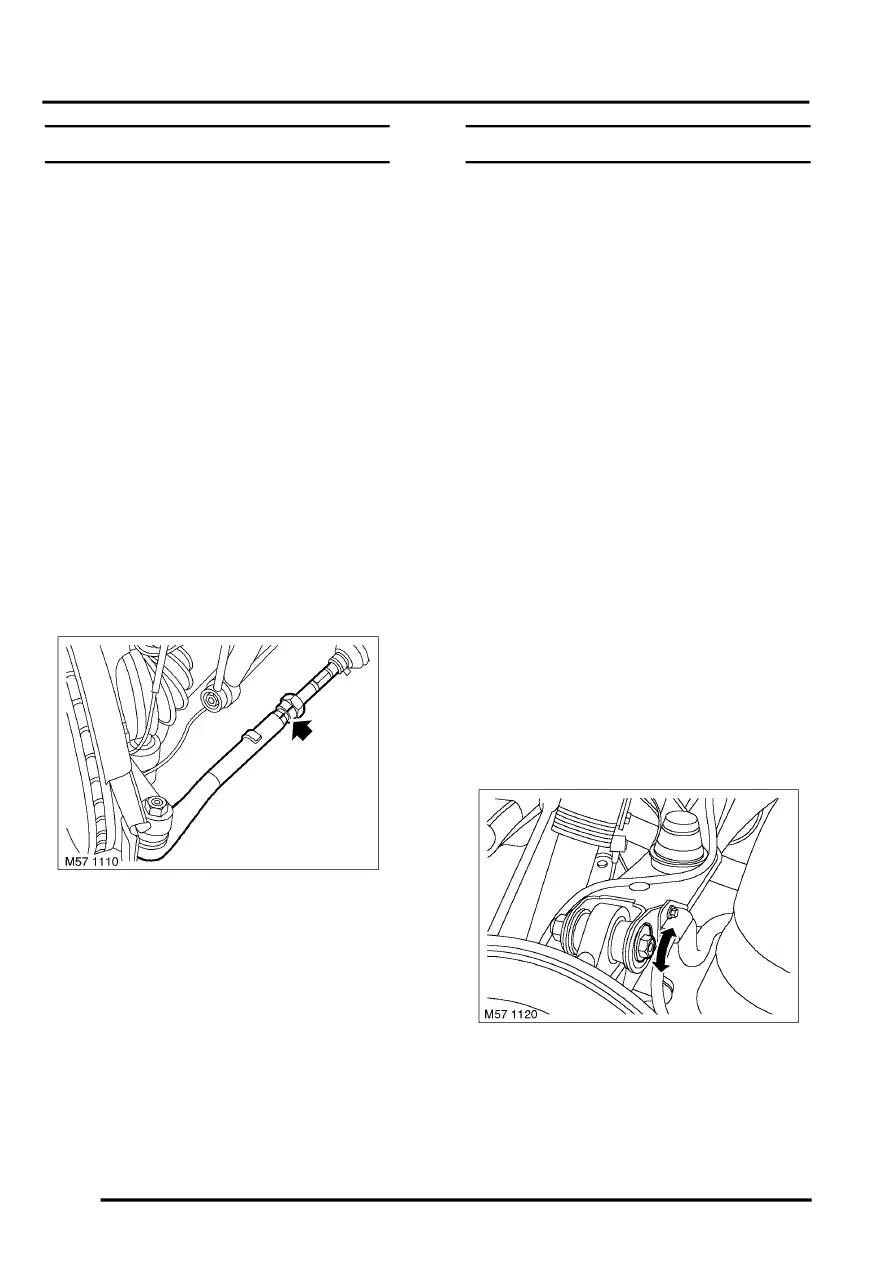
4. Adjust by rotating track rod using hexagon on
shaft. Do not allow gaiter to twist.
CAUTION: Both track rods must be rotated
an equal amount.
5. Recheck front wheel alignment.
6. Tighten track rod end locknut to 55 Nm (40
lbf.ft).
7. Connect battery earth lead.
Steering geometry
$% 57.65.02
A change in camber means a change in toe,
therefore camber must always be adjusted first.
Before disconnecting the battery, ensure all text and
cautions in the battery disconnection section are
observed.
GENERAL INFORMATION, Electrical
Check
1. Check steering joints, suspension joints and
wheel bearings for wear or free play. Adjust or
repair as required.
2. Ensure tyre pressures are correct and vehicle
is at correct ride height.
3. Roll vehicle backwards and forwards to relieve
stresses in steering and suspension.
4. Ensure that wheel alignment equipment is
properly calibrated.
NOTE: Only use four wheel alignment
equipment recommended for use by Land
Rover.
Adjust
1. Disconnect battery earth lead.
2. Observe readings from test equipment and
3. Rear wheel alignment adjust:
4. Adjusting camber:
5. Loosen upper ball joint nut approximately 3/4 of
a turn.
6. Turn eccentric and adjust camber to specified
value.
7. Tighten nut securing upper ball joint to hub to
165 Nm (121 lbf.ft).