
LR3/Disco 3
the center console through an aperture in the transmission tunnel. A quick release fitting seals the emergency release
cable in the aperture. At the parking brake module, a sealing collar on the outer cable is a push fit in the housing of the
parking brake module.
In the center console, a pull ring is installed on the end of the inner cable. The pull ring is designed to fit the hook on the
end of the jack handle which, in combination with a screwdriver shaft, can be used to pull on the cable.
The pull required to release the latch is approximately 200 N (45 lbf). When the pull ring of the emergency release cable
is released, the spring in the parking brake module retracts the inner cable and the nipple moves away from the pawl
operating lever.
After the emergency release cable has been used to release the parking brake, the next time an apply selection is made
with the parking brake switch, the parking brake module automatically runs through a latching procedure to reconnect the
spline shaft with the force sensor. The parking brake module turns the spline shaft so that it moves towards the force
sensor. The pawl of the spline shaft then re-engages with the spigot of the force sensor. A second apply selection with the
parking brake switch is required to apply the parking brake.
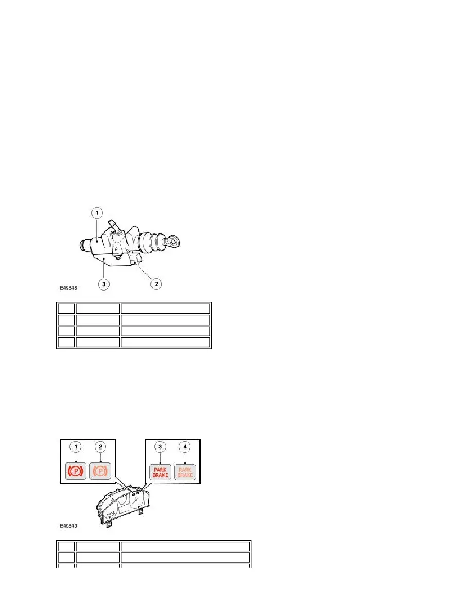
CLUTCH PEDAL POSITION SENSOR (MANUAL TRANSMISSION MODELS ONLY)
The clutch pedal position sensor supplies a signal of clutch pedal position to the parking brake module.
The clutch pedal position sensor is a Hall effect sensor which is attached to the side of the clutch master cylinder. The
position of the piston in the clutch master cylinder effects a magnetic field in the sensor, and is translated by the sensor
into an analogue voltage signal for the parking brake module. The parking brake module relates the signal to the position
of the clutch pedal.
PARKING BRAKE INDICATORS
Item Part Number
Description
1
Clutch master cylinder
2
Electrical connector
3
Clutch pedal position sensor
Item Part Number
Description
1
Red warning indicator (all except NAS)