
LR3/Disco 3
The vacuum pump consists of a radial vane pump driven by an electric motor. The rotor and vanes of the pump are made
from a self-lubricating carbon based material. A stub pipe is installed in the inlet of the pump to provide a connection point
for the vacuum pipe from the brake booster. A second stub pipe, which is covered by a rubber shroud, is installed in the
outlet from the pump.
Operation of the vacuum pump is controlled by the Engine Control Module (ECM), which uses the brake vacuum pump
relay in the Battery Junction Box (BJB) to switch power to the vacuum pump. The ECM controls the time for which the
vacuum pump is switched on and has in-built safeguards to protect the pump from overuse, e.g. continuous running is not
allowed so a minimum delay time is specified between applications.
VACUUM PUMP (2.7L DIESEL)
A vacuum pump is installed on diesel models as the air inlet system does not produce sufficient vacuum for satisfactory
operation of the brake booster.
The vacuum pump is a radial vane pump which is attached to the rear of the RH cylinder head and driven at half engine
speed by the exhaust camshaft. The vacuum pipe from the brake booster connects to an elbow on the rim of the vacuum
pump.
The vacuum pump is lubricated and cooled by engine oil supplied to a port in the front face of the vacuum pump from a
gallery in the cylinder head. The oil return is through a vent in the front face of the pump into a drain cavity in the cylinder
head. Air extracted from the brake booster is vented into the drain cavity with the returning engine oil.
VACUUM PUMP CONTROL DIAGRAM (4.0L AND 4.4L)
NOTE :
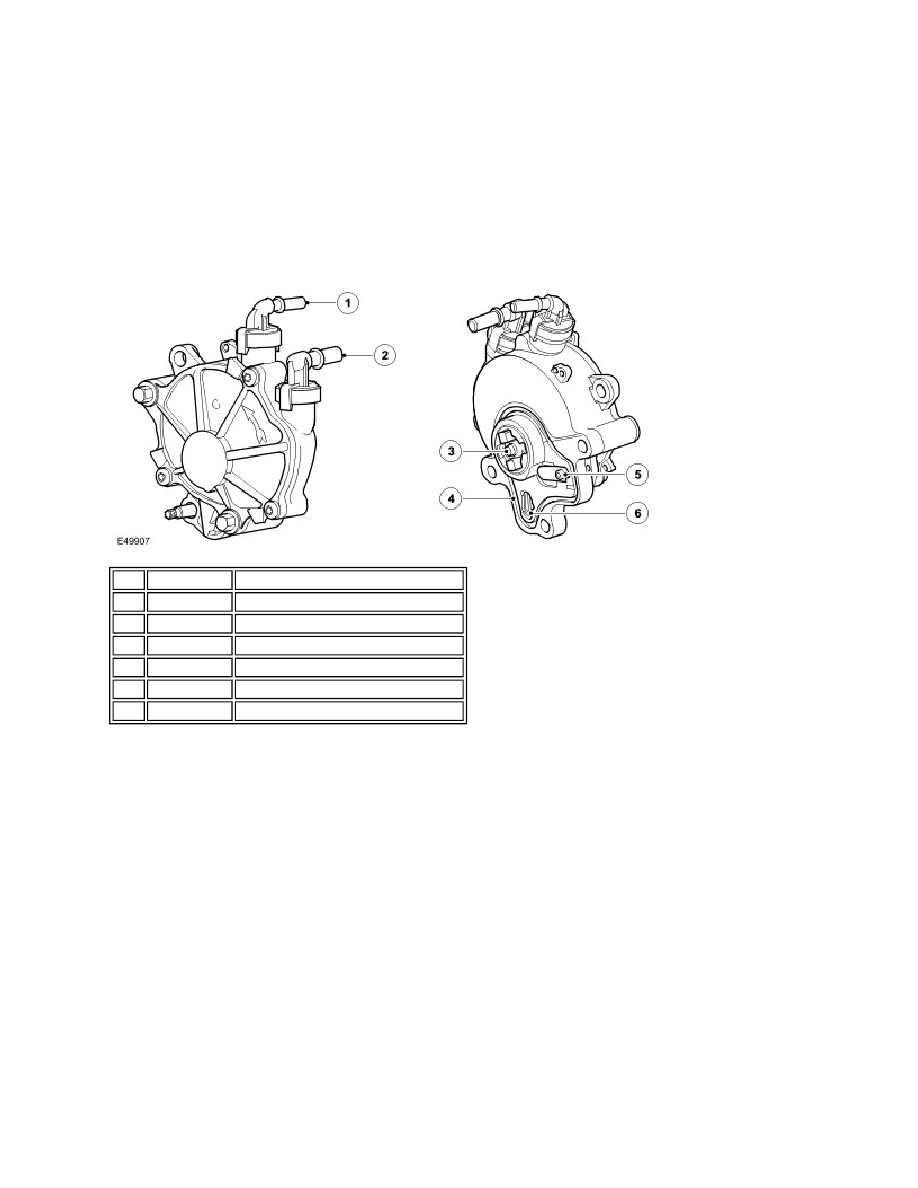
Item Part Number
Description
1
-
Vacuum connection (not used)
2
-
Vacuum connection for brake booster
3
-
Drive dog
4
-
Seal
5
-
Oil inlet port
6
-
Oil return/air vent
A = Hardwired connection