
LR3/Disco 3
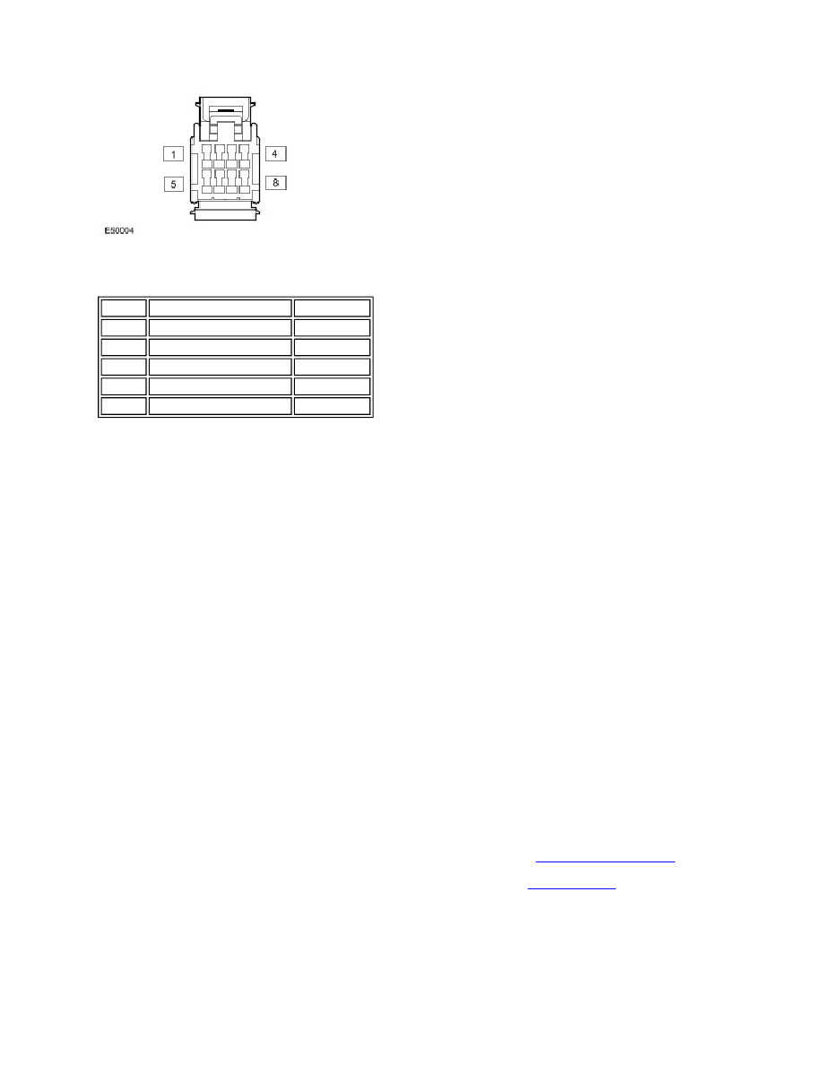
Steering Angle Sensor Harness Connector C0862 Pin Details
WARNING INDICATORS
The following anti-lock control - traction control indicators are installed in the instrument cluster:
ABS Warning Indicator
The ABS warning indicator is an amber colored indicator located between the coolant temperature gage and the fuel level
gage.
The ABS warning indicator is continuously illuminated if there is a fault that affects ABS performance or causes the ABS
function to be disabled.
Operation of the ABS warning indicator is controlled by a high speed CAN bus message from the ABS module to the
instrument cluster.
When the ignition switch is first turned to position II, the ABS warning indicator illuminates for approximately 3 seconds as
a bulb check. During the bulb check, if a fault is stored in the memory of the ABS module, the ABS warning indicator goes
off for 0.5 second, 0.5 second after the start of the bulb check. If a fault during the previous ignition cycle caused the ABS
warning indicator to be illuminated, the ABS warning indicator may remain illuminated after the next bulb check, even if
the fault has been rectified and cleared from the ABS module; the ABS warning indicator remains illuminated until vehicle
speed reaches 15-20 km/h (9.5-12.5 mph) while additional checks of the related inputs are performed.
Brake Warning Indicator
The brake warning indicator is a dual colored indicator, located in the coolant temperature gage, that illuminates amber
for EBA faults and red for EBD faults. The brake warning indicator is also used to give warnings of:
Low brake fluid level (illuminates red). For additional information, refer to
Hydraulic Brake Actuation
(206-06
Hydraulic Brake Actuation)
Brake pad wear (illuminates amber). For additional information, refer to
Rear Disc Brake
(206-04 Rear Disc
Brake)
Operation of the brake warning indicator is controlled by a high speed CAN bus message from the ABS module to the
instrument cluster.
When the ignition switch is first turned to position II, the brake warning indicator illuminates amber for approximately 1.5
seconds then red for approximately 1.5 seconds, as a bulb check.
Pin No.
Description
Input/Output
1 to 4
Not used
-
5
Ignition power supply
Input
6
High speed CAN bus high Input/Output
7
High speed CAN bus low Input/Output
8
Ground
-