
LR3/Disco 3
separate outlet ports to the rear brakes. Each of the circuits in the HCU contain the following components to control the
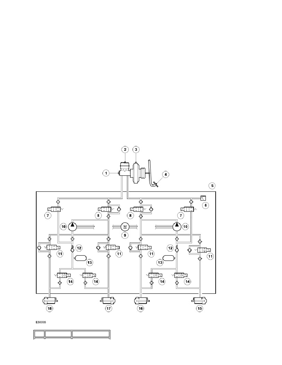
supply of hydraulic pressure to the brakes:
A normally open, solenoid operated, pilot valve, to enable active braking.
A normally closed, solenoid operated, priming valve, to connect the brake fluid reservoir to the return pump during
active braking.
A return pump, to generate hydraulic pressure for active braking and return brake fluid to the reservoir.
Normally open, solenoid operated, inlet valves and normally closed, solenoid operated, outlet valves, to modulate
the hydraulic pressure in the individual brakes.
An accumulator and a relief valve, to allow the fast release of pressure from the brakes.
Filters, to protect the components from contamination.
The primary circuit also incorporates a pressure sensor to provide the ABS module with a hydraulic pressure signal.
Contact pins on the HCU mate with contacts on the ABS module to provide the electrical connections from the ABS
module to the return pump motor and the pressure sensor. The solenoids that operate the valves are installed in the ABS
module.
Replacement HCU are supplied pre-filled. After installation on the vehicle, T4 must be used to operate the solenoid valves
and the return pump to ensure correct bleeding of the HCU and brake circuits.
Schematic of HCU
Item Part Number
Description