
LR3/Disco 3
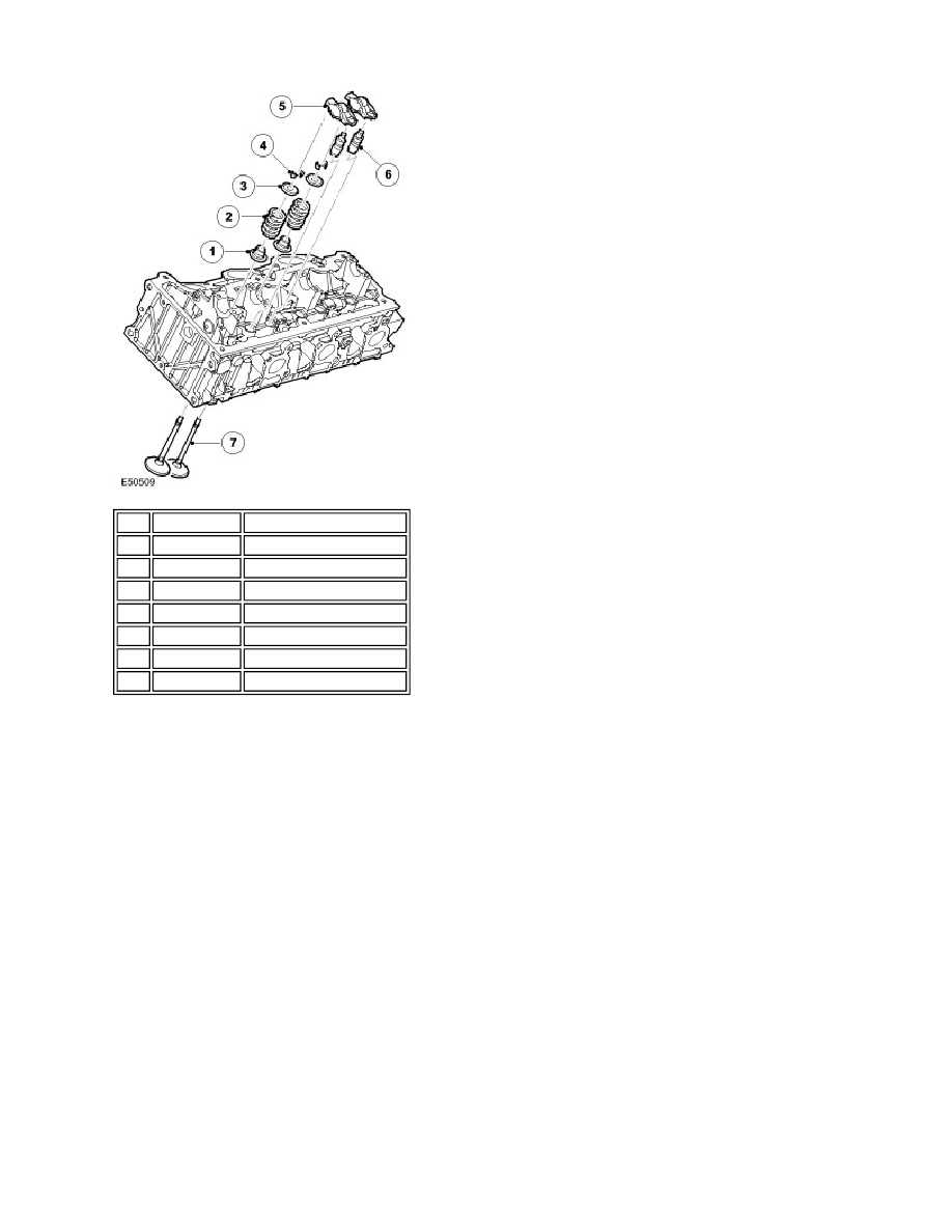
The valve springs are made from spring steel and are of the parallel single-coil type. The bottom end of each spring rests
on the flange of a spring retainer, which has an integral valve stem seal. The top end of the spring is held in place by a
spring retainer, which is held in position at the top end of the valve stem by split taper collets. The taper collets have
grooves on the internal bore that locate to grooves ground into the upper stems of the valves.
Valve seats and valve guides are an interference fit in the cylinder head.
The valves are operated through roller-type finger rockers and hydraulic lash adjusters, actuated by the camshaft lobes.
When the camshaft lobe presses down on the top of a finger rocker, roller mechanism, the respective valve is forced
down, opening the affected inlet or exhaust valve. The use of this type of actuation method helps reduce friction in the
valve timing mechanism.
The body of the hydraulic lash adjusters contains a plunger and two chambers for oil feed and pressurised oil. The
pressurised oil is supplied to the lash adjusters via the main oil galleries in the cylinder head and through a hole in the
side of the lash adjuster body. The oil passes into a feed chamber in the lash adjuster and then through to a separate
pressure chamber via a one way ball valve.
Oil flow from the pressure chamber is determined by the amount of clearance between the lash adjuster outer body and
the centre plunger. Oil escapes up the side of the plunger every time the lash adjuster is operated, the downward
pressure on the plunger forcing a corresponding amount of oil in the lash adjuster body to be displaced. When the
downward pressure from the camshaft and finger rocker is removed (i.e. after the trailing flank of the camshaft lobe has
passed), oil pressure forces the lash adjuster's plunger up again. This pressure is not sufficient to effect the valve
operation, but eliminates the clearance between the finger rocker and top of the valve stem.
Valve Rocker Arm Oil Supply Tube
Item Part Number
Description
1
-
Valve stem seal
2
-
Valve spring
3
-
Valve spring retainer seat
4
-
Valve spring retainer key
5
-
Rocker arm
6
-
Hydraulic lash adjuster
7
-
Valve