
LR3/Disco 3
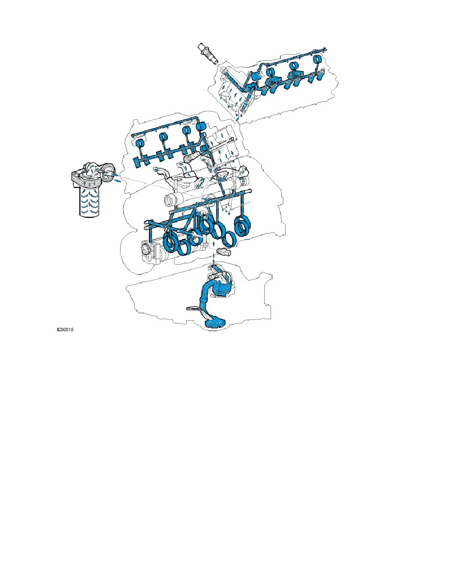
The lubrication system is of the full-flow filtration, force-fed type.
Oil is drawn, via a strainer and pick-up pipe in the sump into the jackshaft driven oil pump which has an integral pressure
relief valve. The strainer in the pick-up pipe prevents any ingress of foreign particles from passing through to the inlet side
of the oil pump and damaging the oil pump and restricting oil drillings. The oil pressure relief valve in the oil pump opens if
the oil pressure becomes excessive and diverts oil back around the pump.
Pressurised oil is pumped through the oil filter, mounted on the oil pump housing. The lubrication system is designed so
that a higher proportion of oil flow is directed to the cylinder block main oil gallery while a lower proportion of oil flow,
(controlled by a restrictor in the oil filter housing), is directed to the engine oil cooler (if fitted). The remainder of the oil flow
from the outlet side of the oil filter is combined with the return flow from the oil cooler (if fitted) before being passed into
the cylinder block main oil gallery.
The main oil gallery has drillings that direct the oil to each cylinder head and the main bearings. Cross drillings in the
crankshaft main bearings carry the oil to the connecting rod big-end bearings. Oil galleries in the cylinder head carry the
oil to the camshafts and the hydraulic lash adjusters.
The oil pressure switch is located in the cylinder block to sense the oil pressure level before the oil flow enters the main
gallery in the cylinder block. A warning lamp in the instrument cluster is illuminated if low oil pressure is detected.
Oil at reduced pressure is directed to each cylinder bank via two restrictors in the cylinder block/cylinder head locating
dowels, one at the front on the LH bank and the other at the rear on the RH bank. Oil then passes through a drilling in the
cylinder head to the camshaft carrier, where it is directed via separate galleries to the camshaft bearings and hydraulic
tappet housings. Return oil from the cylinder head drains into the sump via the cylinder head bolt passages.
Oil Level Gauge