
LR3/Disco 3
The connecting rods are manufactured from sinter-forged steel and have fracture-split bearing caps. The bearing caps
are produced by fracturing the opposing sides of the connecting rod at the bearing horizontal centre line. As well as being
easier to manufacture, when reassembled the fractured surfaces interlock to form a strong seamless joint. The cylinder
position is marked on adjoining sides of the joint to identify matching connecting rods and bearing caps. The connecting
rod bearings are aluminium/tin split plain bearings.
The pistons are of the open-ended skirt design. Three piston rings, two compression and one oil control, are installed on
each piston. Each piston is installed on a gudgeon pin located in a aluminium/tin bushing in the connecting rod.
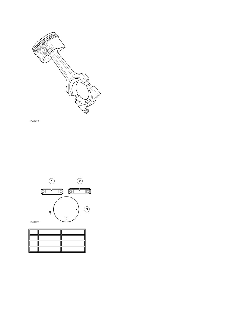
Connecting Rod and Piston Installation
The piston grade number is stamped on the crown of the piston and must coincide with that for each cylinder bore. The
piston must be assembled in the correct orientation for the designated cylinder bore:
Bank 'A' - piston grade number and the thick flange of the connecting rod must face the front of the engine
Bank 'B' - piston grade number and the thin flange of the connecting rod must face the front of the engine
Crankshaft Position Sensor
Item Part Number Description
1
-
Bank A (RHS)
2
-
Bank B (LHS)
3
-
Piston