
LR3/Disco 3
The trigger wheel is located on the rear of the crankshaft. It is pressed onto the crankshaft using a special tool, which also
precisely aligns the trigger wheel for crankshaft position and timing. The trigger wheel consists of 60 magnets, minus 2 for
ECM crankshaft position reference and synchronisation. The magnets cannot be seen on the trigger-wheel; therefore, it
can only be positioned using the special tool.
The CKP sensor air gap is 0.4mm to 0.5mm there is no adjustment. The sensor bolts into the rear oil seal retainer and the
tolerance on the retainer and sensor gives an air gap within the specified range.
NOTE :
Main Bearings
The main bearings are aluminium/tin split plain selective bearings. An oil groove in the top half of each bearing transfers
oil into the crankshaft for lubrication of the connecting rod bearings. The upper and lower shells of bearing number four
contain integral thrust washers, which limits the end float of the crankshaft.
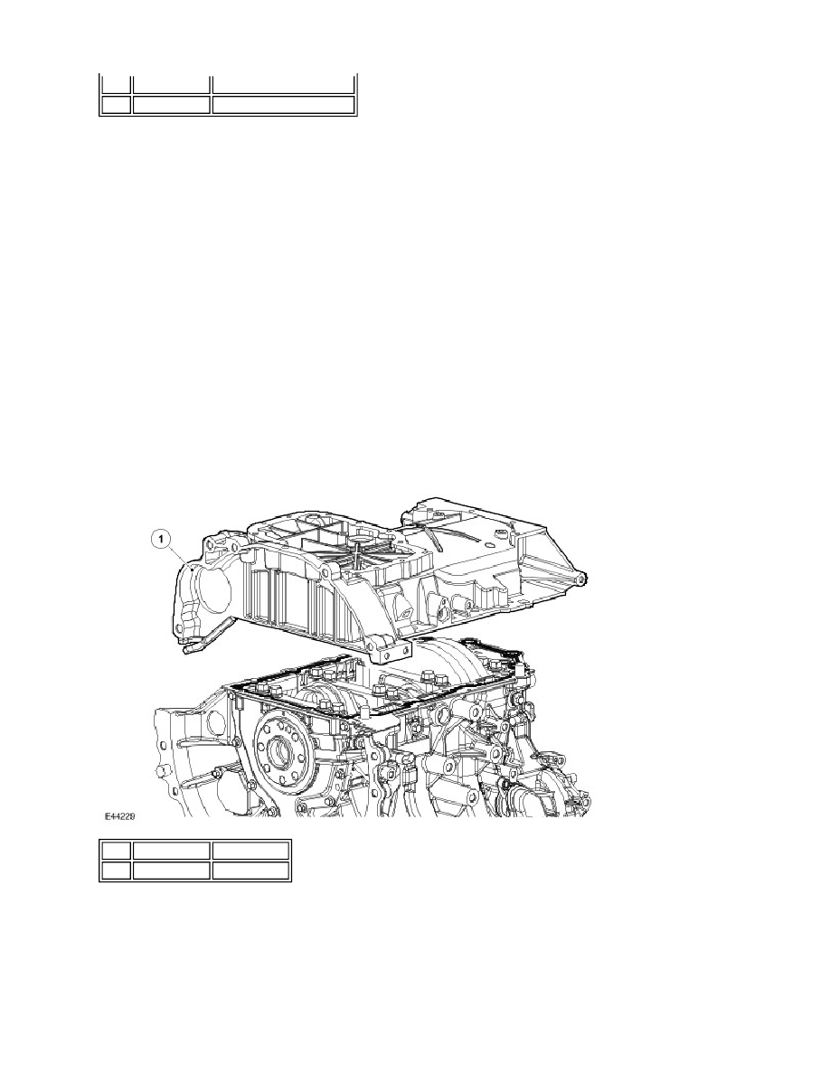
Ladder Frame
The ladder frame is fitted to the lower cylinder block to stiffen the base structure thus helping to reduce Noise, Vibration
and Harshness (NVH). The frame is made of high-pressure die cast aluminium and also incorporates an oil baffle plate to
reduce oil foaming and slosh.
The ladder frame is secured to the cylinder block with 2 dowels, 2 locator pins for the gasket and 18 retaining bolts; three
different lengths of bolts are used:
Item Part Number
Description
1
-
CKP sensor trigger wheel
If the trigger wheel is removed for any reason, a new trigger wheel must be fitted. Do not reuse the old trigger
wheel.
Item Part Number Description
1
-
Ladder frame