
LR3/Disco 3
gasket thickness is dependent on the maximum piston protrusion. Gasket thickness is identified by serrations cut into the
front end of the gasket.
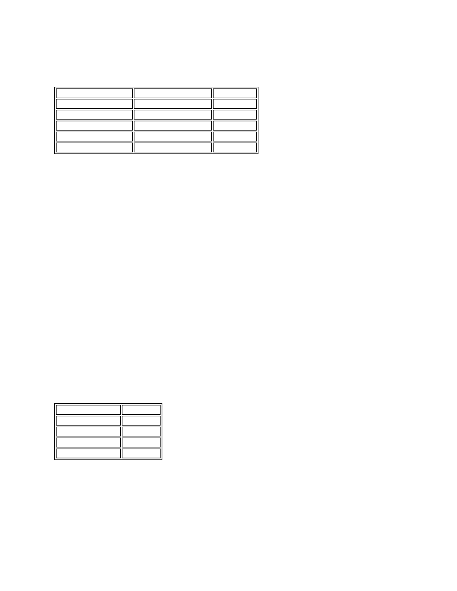
Gasket Selection Table
To calculate the correct cylinder head gasket thickness, each piston must be measured at two points, with an average of
the two measurements taken to determine the piston protrusion. The highest of the three measurements will determine
the gasket required for that particular cylinder head.
NOTE :
Camshafts
The camshafts are of a hollow steel tube construction, with pressed on sintered lobes. Each camshaft is retained by
aluminium alloy caps, five for the exhaust camshafts and four for the inlet camshafts. Location letters, A to I for the intake
camshaft and R to Z for the exhaust camshaft, are marked on the outer faces of the caps for each cylinder head.
The LH cylinder bank exhaust camshaft is machined to accept a rear camshaft gear. The rear camshaft gear provides
drive for High Pressure (HP) fuel pump, located centrally at the rear of the 'vee', via a short-toothed belt and tensioner
pulley.
The RH cylinder head exhaust camshaft is machined at the rear end to provide a drive connection for the vacuum pump.
NOTE :
Camshaft Timing
Inlet and Exhaust Valves
Piston Protrusion (mm) Gasket Thickness (mm) Identification
0.541 - 0.590
1.12
1
0.591 - 0.640
1.17
2
0.641 - 0.690
1.22
3
0.691 - 0.740
1.27
4
0.741 - 0.790
1.32
5
The difference between the maximum and minimum protrusion measurement in any one bank should not be
greater than 0.1mm. It is permissible to have a different grade of gaskets between the LH and RH banks.
The camshaft drive sprockets also form the thrust faces for the camshaft endfloat. In production the endfloat is
0.065mm to 0.185mm. In service, if the endfloat is out of specification, the camshaft(s) or cylinder head(s) may
have to be replaced.
Valve
Position
Inlet valve opens
8.5° BTDC
Inlet valve closes
35.5° ABDC
Exhaust valve opens 64° BBDC
Exhaust valve closes 12° ATDC