
LR3/Disco 3
pressure. Excess fuel from the pressure regulator is directed to the front jet pump. The controlled pressure provides more
fuel to the fuel rail than the maximum requirement of the engine; therefore a constant pressure is maintained in the rail
under all operating conditions. For additional information, refer to
Fuel Tank and Lines
(310-01A Fuel Tank and Lines -
4.0L)
The fuel pump is controlled by the ECM via a fuel pump relay, which is located in the Battery Junction Box (BJB).
When the ignition is switched to position II, the ECM provides an earth path for the coil of the fuel pump relay on pin 95 of
ECM connector C0634. The relay is energised for a short period to pressurise the fuel system. When the ECM senses
that the engine is being cranked by receipt of a valid signal from the Crankshaft Position (CKP) sensor, the ECM
energises the fuel pump relay for as long as the engine is running. For additional information, refer to
Electronic Engine
Controls
(303-14A Electronic Engine Controls - 4.0L)
THROTTLE BODY
The throttle body is located centrally at the front of the intake manifold. The engine torque is controlled by the electronic
throttle body. An electronic pedal assembly determines throttle opening. The signal from the pedal assembly is sent to the
EMS and the throttle is opened to the correct angle by means of an electric motor integrated into the throttle body.
Sensors in the throttle body are used to determine the position of the throttle plate and the rate of change in its angle. For
additional information, refer to
Electronic Engine Controls
(303-14A Electronic Engine Controls - 4.0L)
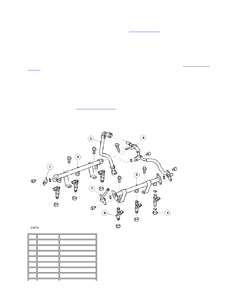
FUEL RAIL
Item Part Number
Description
1
-
Fuel pressure regulator
2
-
RH fuel rail
3
-
Fuel jump hose
4
-
Fuel supply pipe
5
-
LH fuel rail
6
-
Injector seat inserts
7
-
Schraeder valve