
LR3/Disco 3
The V6 engine torque is regulated via an electronic throttle body which is located on the intake manifold in the engine
compartment. An Accelerator Pedal Position sensor (APP) determines the driver demand to control throttle opening. This
value is input into the EMS and the throttle is opened to the correct angle by means of an electric motor integrated into
the throttle body. Sensors in the throttle body are used to determine the position of the throttle plate and the rate of
change in its angle. A software strategy within the ECM enables the throttle position to be calibrated each ignition cycle.
When the ignition is turned 'ON', the ECM opens and closes the throttle fully, thus performing a self-diagnostic and
calibration. The throttle body is connected to the ECM via a pair of twisted wires to avoid electrical interference. For
additional information, refer to
Acceleration Control
(310-02A Acceleration Control - 4.0L)
C0175 Electronic Throttle Pin Out Table
ACCELERATOR PEDAL POSITION SENSOR (APP)
The Accelerator Pedal Position Sensor (APP) is used in conjunction with the Electronic Throttle Body to provide a drive-
by-wire system. The sensor is a resistive type. Sensors in the accelerator pedal are used to determine the driver's request
for vehicle speed, acceleration and deceleration. This value is input into the EMS and the throttle is opened to the correct
angle by means of an electric motor integrated into the throttle body.
The APP sensor signals are checked for range, and for plausibility. Two separate reference voltages are supplied to the
pedal. If one sensor fails, the other can be used as a 'limp – home' input.
The wires that connect the ground and signal from both potentiometers to the EMS are twisted together into two pairs,
avoiding having to use a screen wire.
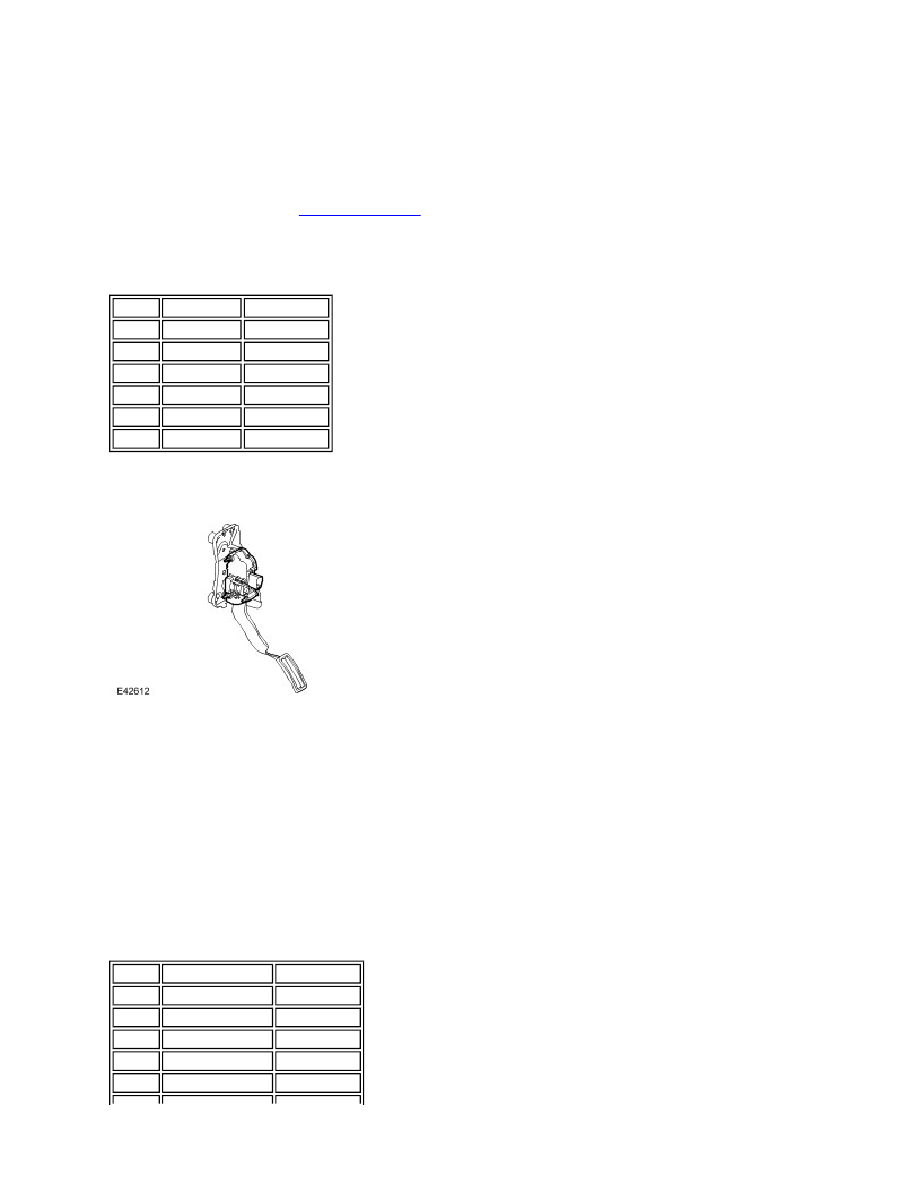
If signal failure occurs, the ECM enters limp home mode. The APP Sensor is located at the accelerator pedal .
C0787 APP Sensor Connector Pin Out Table
Pin No Description Input/Output
1
Signal 1
Output
2
5 volt supply
Input
3
Signal 2
Output
4
Ground
-
5
Actuator +
Input
6
Actuator -
-
Pin No
Description
Input/Output
1
Sensor 2 ground
-
2
Sensor 1 demand
Output
3
Sensor 1 ground
-
4
NC
-
5
Sensor 2 demand
Output