
LR3/Disco 3
The V6 ECM incorporates a cruise control function. Active Cruise Control (ACC) is also an option. The EMS uses a set of
resistive ladders to interface with the driver cruise control requirements. The cruise control is operated from the steering
wheel mounted switches. There are three illuminated rocker switches on a resistive ladder. For additional information,
refer to
Speed Control
(310-03A Speed Control)
The cruise control does not have a master switch, it is enabled by pressing the set switch.
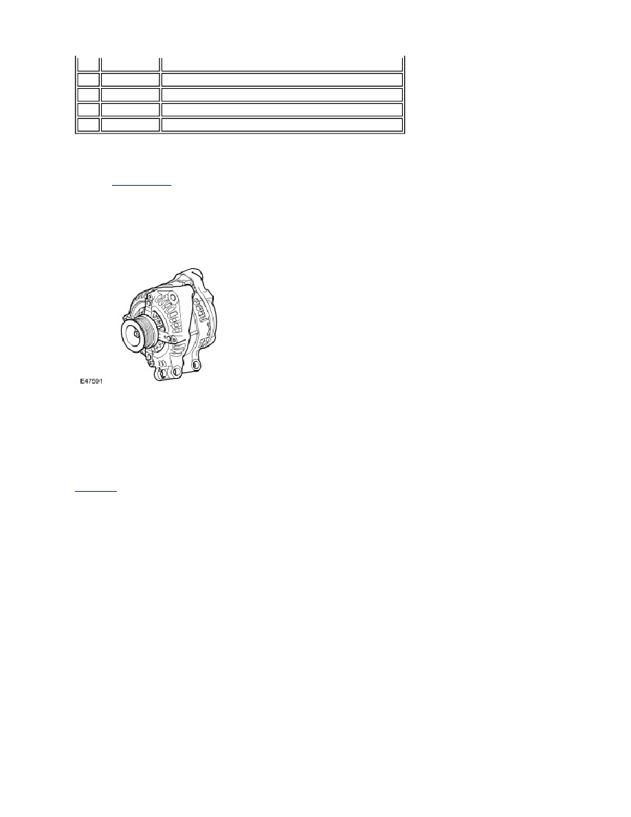
GENERATOR
The Generator has a multi function voltage regulator for use in a 14V charging system with 6÷12 zener diode bridge
rectifiers.
The ECM monitors the load on the electrical system via PWM signal and adjusts the generator output to match the
required load. The ECM also monitors the battery temperature to determine the generator regulator set point. This
characteristic is necessary to protect the battery; at low temperatures battery charge acceptance is very poor so the
voltage needs to be high to maximise any recharge ability, but at high temperatures the charge voltage must be restricted
to prevent excessive gassing of the battery with consequent water loss. For additional information, refer to
Generator
(414-02A Generator and Regulator - 4.0L)
The Generator has a smart charge capability that will reduce the electrical load on the Generator reducing torque
requirements, this is implemented to utilise the engine torque for other purposes. This is achieved by monitoring three
signals to the ECM:
Generator sense (A sense), measures the battery voltage at the CJB.
Generator communication (Alt Com) communicates desired Generator voltage set point from ECM to Generator.
Generator monitor (Alt Mon) communicates the extent of Generator current draw to ECM. This signal also
transmits faults to the ECM which will then sends a message to the instrument pack on the CAN bus to illuminate
the charge warning lamp.
FUEL INJECTORS
1
On/Suspend/Off Switch
2
Resume/Accelerate/Decelerate (+/–) Switches
3
Active cruise control time gap switches (for future release)
4
Clock spring
5
Wiper control column switch