
LR3/Disco 3
transmits faults to the ECM which will then sends a message to the instrument pack on the CAN bus to illuminate
the charge warning lamp. For additional information, refer to
Generator
(414-02B Generator and Regulator -
4.4L)
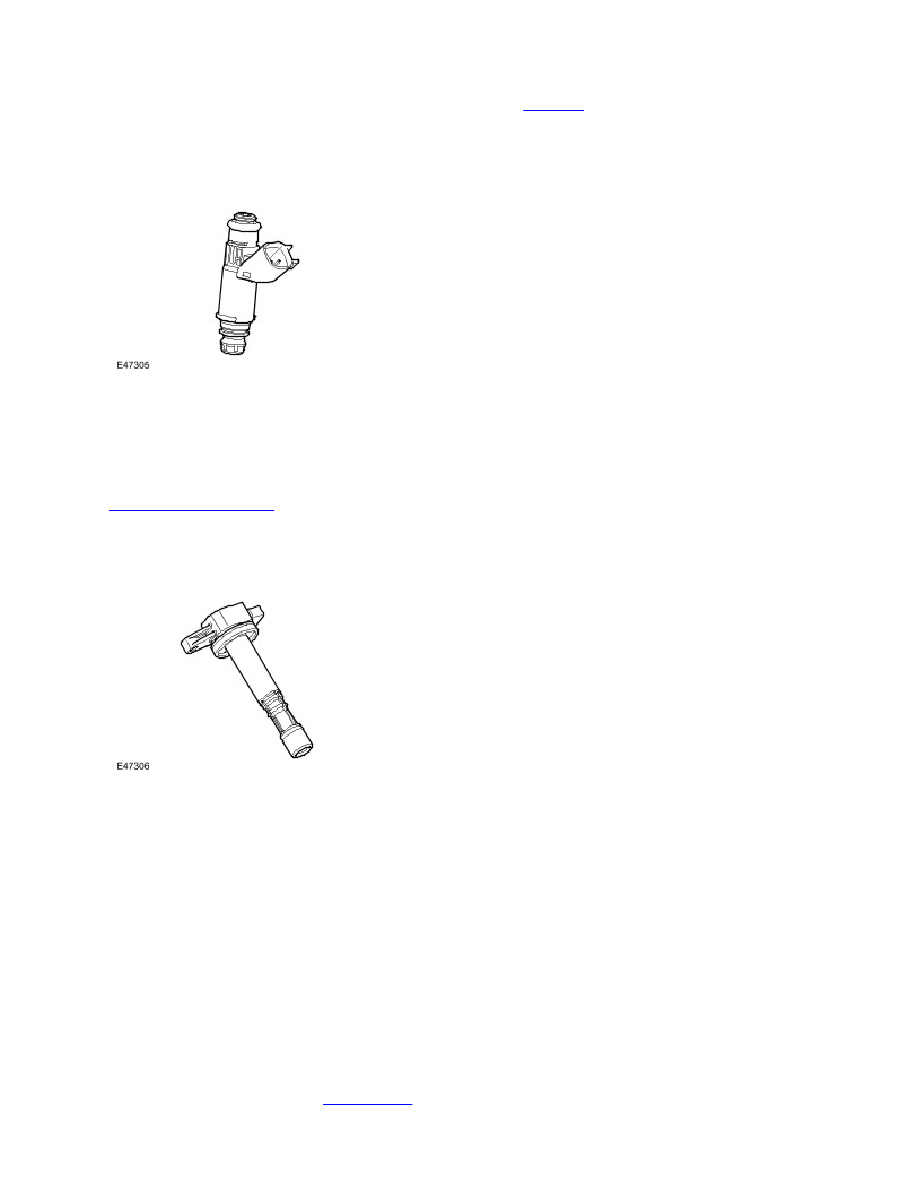
FUEL INJECTORS
The engine has 8 fuel injectors (one per cylinder), each injector is directly driven by the ECM. The injectors are fed by a
common fuel rail as part of a ‘returnless’ fuel system. The fuel rail pressure is regulated to 4.5 bar by a fuel pressure
regulator which is integral to the fuel pump module, within the fuel tank. The injectors can be checked by resistance
checks. There is a fuel pressure test Schrader valve attached to the fuel rail on the front LH side for fuel pressure testing
purposes. The ECM monitors the output power stages of the injector drivers for electrical faults.
The injectors have a resistance of 13.8 Ohms ± 0.7 Ohms @ 20 Degrees Celsius For additional information, refer to
Fuel Charging and Controls
(303-04B Fuel Charging and Controls - 4.4L)
IGNITION COILS
The V8 engine is fitted with eight plug-top coils that are driven directly by the ECM. This means that the ECM, at the point
where sufficient charge has built up, switches the primary circuit of each coil and a spark is produced in the spark plug.
The positive supply to the coil is fed from a common fuse. Each coil contains a power stage to trigger the primary current.
The ECM sends a signal to each of the coils power stage to trigger the power stage switching. Each bank has a feedback
signal that is connected to each power stage. If the coil power stage has a failure the feedback signal is not sent, causing
the ECM to store a fault code appropriate to the failure.
The ECM calculates the dwell time depending on battery voltage and engine speed to ensure constant secondary energy.
This ensures sufficient secondary (spark) energy is always available, without excessive primary current flow thus avoiding
overheating or damage to the coils.
The individual cylinder spark timing is calculated from a variety of inputs:
Engine speed and load.
Engine temperature.
Knock control.
Auto gearbox shift control.
Idle speed control.
For additional information, refer to
Engine Ignition
(303-07B Engine Ignition - 4.4L)