
LR3/Disco 3
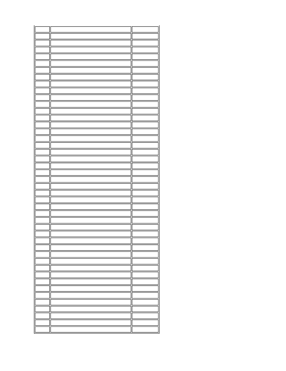
A4
CAN High
Input/Output
B1
Starter motor enable
Output
B2
APP sensor ground
-
B3
Radiator outlet temperature sensor ground
-
B4
Speed control
Input
C1
APP 1 Sensor ground
-
C2
APP sensor 2 reference voltage
Output
C3
ECT sensor 2
Output
C4
Speed control
Input
D1
APP 1 signal
Input
D2
APP 2 Sensor ground
-
D3
Voltage 2
Input
D4
Not used
-
E1
APP sensor 1 reference voltage
Output
E2
Water in fuel sensor
Input
E3
Stop switch 1
Input
E4
Inertia switch
Input
F1
Intake air temperature sensor
Input
F2
Not used
-
F3
Engine cranking signal
Input
F4
Mass air flow sensor
Input
G1
Fuel pump power monitor
Input
G2
Stop light switch
Input
G3
Not used
-
G4
Not used
-
H1
Not used
-
H2
Not used
-
H3
Not used
-
H4
Not used
-
J1
Not used
-
J2
E box fan
Output
J3
Main relay
Output
J4
Fuel pump relay
Output
K1
Not used
-
K2
Electric cooling fan control
Output
K3
Ignition switch sense
Input
K4
Keep alive power supply
Input
L1
Battery voltage
Input
L2
Battery voltage
Input
L3
Battery voltage
Input
L4
Ground
-
M1
Ground
-
M2
Ground
-
M3
Ground
-
M4
Ground
-