
LR3/Disco 3
Cooling fan operation
Glow plug activation time.
The instrument cluster uses the temperature information for temperature gauge operation. The engine coolant
temperature signal is also transmitted on the CAN bus by the instrument cluster for use by other systems.
The ECM ECT sensor circuit consists of an internal voltage divider circuit which incorporates an NTC thermistor. As the
coolant temperature rises the resistance through the sensor decreases and vice versa. The output from the sensor is the
change in voltage as the thermistor allows more current to pass to earth relative to the temperature of the coolant.
The ECM compares the signal voltage to stored values and adjusts fuel delivery to ensure optimum driveability at all
times. The engine will require more fuel when it is cold to overcome fuel condensing on the cold metal surfaces inside the
combustion chamber. To achieve a richer air/fuel ratio, the ECM extends the injector opening time. As the engine warms
up the air/fuel ratio is leaned off.
The input to the sensor is a 5V reference voltage supplied from the voltage divider circuit within the ECM. The ground
from the sensor is also connected to the ECM which measures the returned current and calculates a resistance figure for
the sensor which relates to the coolant temperature.
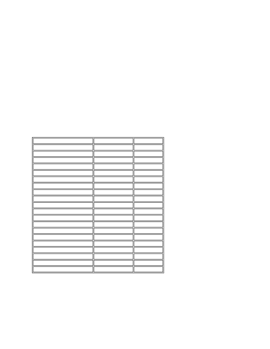
The following table shows engine coolant temperature values and the corresponding sensor resistance and voltage
values.
Coolant Temperature Sensor Response
If the ECT sensor fails, the following symptoms may be observed:
Difficult cold start.
Difficult hot start.
Engine performance compromised.
Temperature gauge inoperative or inaccurate reading.
In the event of ECT sensor signal failure, the ECM applies a default value of 80°Celsius (176°F) coolant temperature for
fuelling purposes. The ECM will also permanently operate the cooling fan at all times when the ignition is switched on, to
Temperature (Degrees Celsius) Resistance (Kohms) Voltage (Volts)
-40
925
4.54
-30
496
4.46
-20
277
4.34
-10
160
4.15
0
96
3.88
10
59
3.52
20
37
3.09
30
24
2.62
40
16
2.15
50
11
1.72
60
7.5
1.34
70
5.6
1.04
80
3.8
0.79
90
2.9
0.64
100
2.08
0.49
110
1.56
0.38
120
1.19
0.29
130
0.918
0.22
140
0.673
0.17
150
0.563
0.14