
LR3/Disco 3
The torque converter used on TdV6 models is similar in construction to the torque converter on petrol models but contains
a torsional vibration damper. The damper smooths the output from the engine and prevents unwanted vibration from
being passed to the transmission.
Impeller
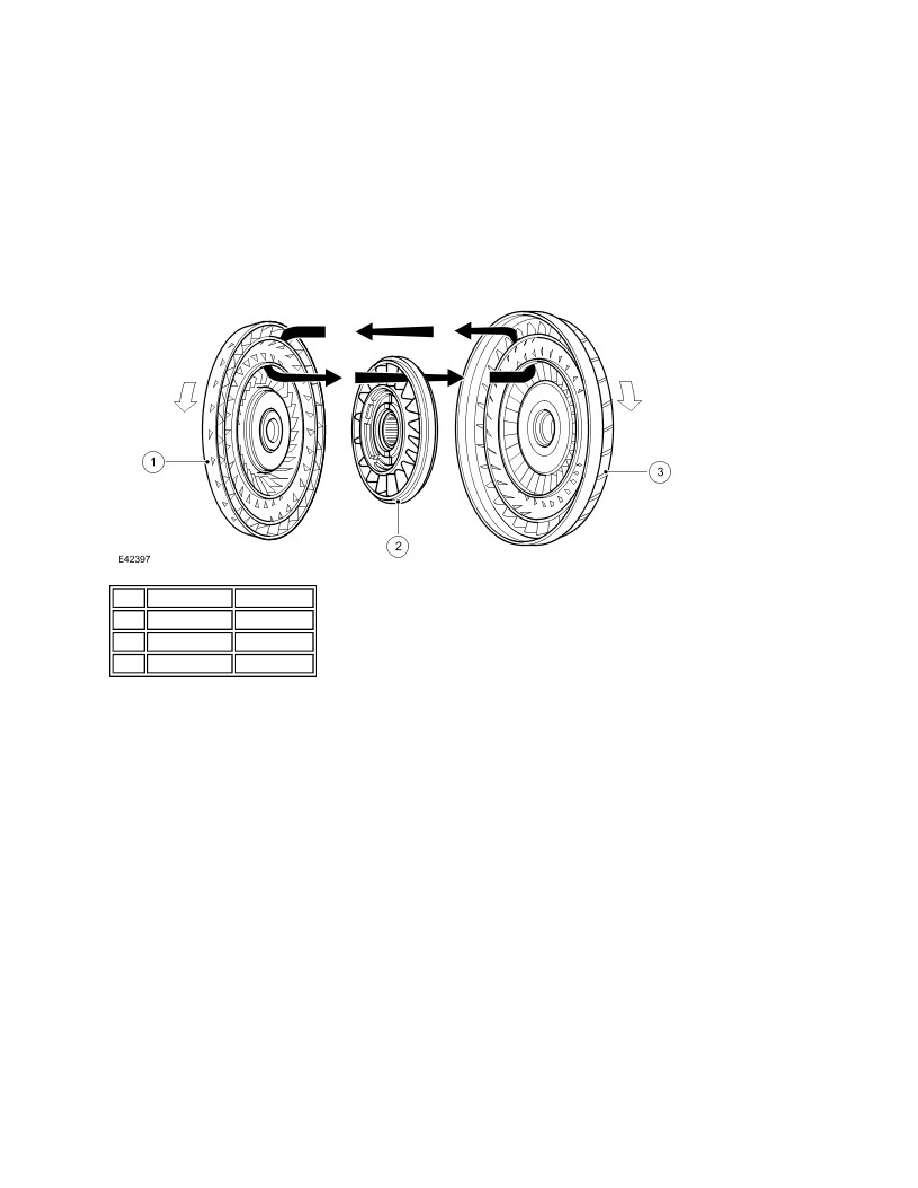
Fluid Flow
NOTE :
When the engine is running the rotating impeller acts as a centrifugal pump, picking up fluid at its centre and discharging
it at high velocity through the blades on its outer rim. The design and shape of the blades and the curve of the impeller
body cause the fluid to rotate in a clockwise direction as it leaves the impeller. This rotation improves the efficiency of the
fluid as it contacts the outer row of blades on the turbine.
The centrifugal force of the fluid leaving the blades of the impeller is passed to the curved inner surface of the turbine via
the tip of the blades. The velocity and clockwise rotation of the fluid causes the turbine to rotate.
Turbine
The turbine is similar in design to the impeller with a continuous row of blades. Fluid from the impeller enters the turbine
through the tip of the blades and is directed around the curved body of the turbine to the root of the blades. The curved
surface redirects the fluid back in the opposite direction to which it entered the turbine, effectively increasing the turning
force applied to the turbine from the impeller. This principle is known as torque multiplication.
When engine speed increases, turbine speed also increases. The fluid leaving the inner row of the turbine blades is
rotated in an anti-clockwise direction due to the curve of the turbine and the shape of the blades. The fluid is now flowing
in the opposite direction to the engine rotation and therefore the impeller. If the fluid was allowed to hit the impeller in this
condition, it would have the effect of applying a brake to the impeller, eliminating the torque multiplication effect. To
prevent this, the stator is located between the impeller and the turbine.
Stator
The stator is located on the splined transmission input shaft via a freewheel clutch. The stator comprises a number of
blades which are aligned in an opposite direction to those of the impeller and turbine. The main function of the stator is to
Typical torque converter shown
Item Part Number Description
1
-
Turbine
2
-
Stator
3
-
Impeller