
LR3/Disco 3
selector lever and the transmission selector shaft.
The switch is electrically connected to the TCM which outputs a common power supply to each of the four switch
contacts. This power supply is also used by the two speed sensors and the fluid temperature sensor. Each of the four
switch contacts have a separate feed input to the TCM which can detect which selector lever position has been selected.
Shift Interlock Solenoid
The shift interlock solenoid is located on the side of the selector lever assembly. The solenoid operates two locking levers
which engage in the lower lever and lock it in the Park (P) and Neutral (N) positions. When the ignition is on or the engine
is running, the solenoid is de-energised and prevents the lever from moving.
When energised, by the depression of the footbrake, the solenoid is energised and the selector lever may be moved from
the P position. If the selector lever is left in the N position for more than 800m/s the solenoid will be energised and the
selector lever will become locked in the N position. To move the selector lever from the N position in this condition the
footbrake must be applied. This prevents the selector lever from being moved to the 'D' or 'R' position unintentionally and
the application of the brakes also prevents the vehicle 'creeping' when the gear is engaged.
Movement of the selector lever from the 'P' or 'N' positions is also prevented if the TCM senses the engine speed is above
2500 rev/min, even if the brake pedal is depressed.
In the event of an electrical failure of the vehicle or failure of the interlock solenoid or its associated wiring, it is possible to
move the selector lever from the Park 'P' position by removing the coin tray on left hand drive vehicles or the trim panel
behind the park brake switch on right hand drive vehicles and lifting the white coloured tab on the rear of the selector
lever assembly. Whilst holding the tab in this position move the selector lever from the 'P' position.
The selector lever will also be locked in the N position during the transfer box changing range from high to low or vice
versa.
Selector Cable
A selector cable is used as a mechanical connection between the selector lever and the transmission. The cable is a
Bowden type cable which is connected to the selector lever. Movement of the lever in the P, R, N or D positions moves
the cable. Movement of the cable is prevented when the selector lever is in the Manual/Sport position.
The cable is passed through a sealing grommet in the floorpan and is attached to a bracket on the transmission. The
inner cable is connected to a lever which is positively attached to the transmission selector shaft.
Movement of the selector lever in the P, R, N or D positions moves the inner cable which in turn moves the lever. The
lever transforms the linear movement of the cable into rotary movement of the selector shaft. The rotation of the shaft
moves the position switch located within the Mechatronic valve block and also moves the manual spool valve to the
applicable position.
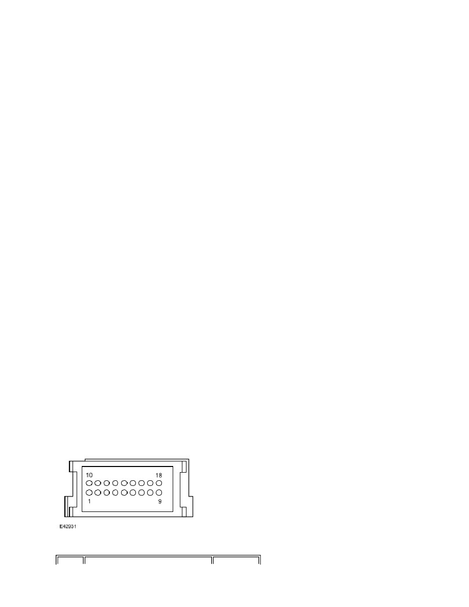
Inputs and Outputs
Connector C2658
The following table shows the connector pin details for the connector on the selector lever assembly.