
LR3/Disco 3
GENERAL
The clutch system is based on the established principle of a single driven plate and diaphragm spring clutch cover
assembly hydraulically actuated from the clutch pedal. Depressing the clutch pedal transfers hydraulic fluid through the
master cylinder, pipework, and slave cylinder ultimately actuating the clutch fingers to release the clutch and thus
disengage drive from the crankshaft. When your foot is off the pedal, the spring pushes the pressure plate against the
clutch disc, which in turn presses against the flywheel, this locks the engine to the transmission input shaft, causing them
to rotate at the same speed.
The clutch system is of conventional design comprising the following major components:
Clutch master cylinder
Clutch pressure pipes
Release bearing/slave cylinder
Clutch Cover assembly
Clutch driven plate
Dual mass flywheel
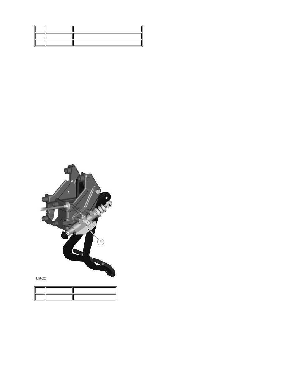
CLUTCH MASTER CYLINDER
The clutch master cylinder is attached directly to the pedal box assembly, located in the driver's footwell.
The cylinder contains a piston assembly, with a push rod connected to the clutch pedal and spring. When the clutch pedal
is depressed, it pushes on the piston, via a linkage. Pressure builds in the cylinder and lines as the clutch pedal is
depressed further.
The cylinder has two hydraulic connections:
7
-
Drive plate
8
-
Dual mass flywheel
9
-
Concentric slave cylinder outlet
Item Part Number
Description
1
-
Clutch master cylinder