
LR3/Disco 3
The control module is responsible for illuminating the 2 'high/low' range change LED's adjacent to the range change lever.
One LED indicates high range and the other indicates low range.
One LED will be on continuously when in the corresponding range.
When changing range, the current range LED will remain on until the new range status has been achieved.
The new range LED will start flashing only when the range change has commenced (i.e. speed and neutral conditions
have been met). The new range LED will be illuminated continuously at the same instant that the current range (now the
old range) LED turns off.
The flash rate is 2 Hz with a 50% duty cycle.
The LED's have 2 levels of intensity, high when the vehicle lights are switch off and low when they are switched on.
If both lights are flashing at 0.5 Hz, this would indicate a transfer box fault or that the transfer box is in undefined range
and may require calibration.
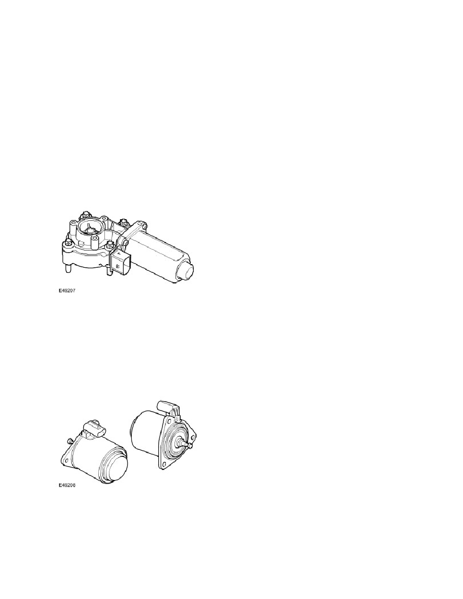
Transfer Box Motor
The transfer box motor provides the necessary movement to perform the high/low range change and the multi-plate clutch
actuation. The motor is located on the rear casing assembly and secured with four bolts.
The motor is a PWM controlled, DC motor with an integrated worm gear reduction drive. It is connected to the transfer box
control module with an eight-pin connector; the power supply of the motor is maintained through two large diameter
cables on the motor connector. An internal position sensor checks the rotational movement of the motor.
There is an temperature sensor located within the motor housing.
Solenoid
The solenoid switches the power flow on the actuation system between high/low range change mode and clutch control
mode. When the solenoid is energized, the solenoid pin deploys and activates the clutch control mode. When the
solenoid is de-energized, the internal spring rejects the solenoid pin and activates the high/low range change mode.
NOTE :
In order to replace the solenoid in service, the solenoid must be energized using the diagnostic tool.