
LR3/Disco 3
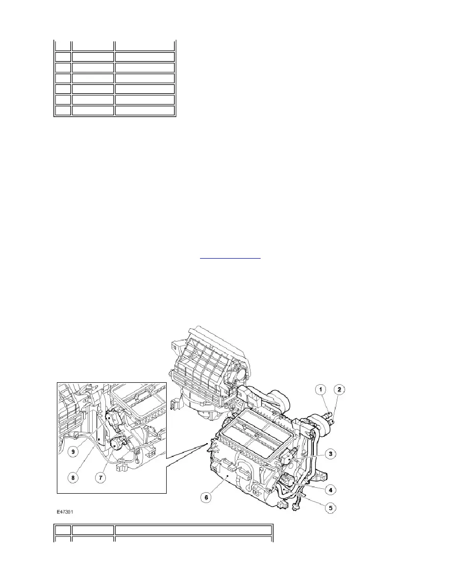
BLOWER
The blower is installed in the air inlet duct, below the cabin air filter, and consists of an open hub, centrifugal fan powered
by an electric motor. Operation of the blower is controlled by the ATCM, using the blower relay in the Battery Junction Box
(BJB) and the blower control module. The blower control module is installed in the air inlet duct downstream of the blower,
where any heat generated during operation is dissipated by the air flow. A wiring harness on the air inlet duct connects
the recirculation door motor, blower and blower control module to the vehicle wiring.
When the blower is required, the ATCM energizes the coil of the blower relay. The energized blower relay supplies battery
power to the blower motor, which is connected to ground through the blower control module. The speed of the blower is
controlled by the blower control module, which regulates the blower motor voltage in response to a Pulse Width
Modulated (PWM) signal from the ATCM. To vary the blower motor voltage the ATCM varies the duty cycle of the PWM
signal.
When the blower is in the automatic mode the ATCM determines the blower speed required from the comfort algorithms.
When the blower is in the manual mode, the ATCM operates the blower at one of seven fixed speeds as selected on the
control panel. For additional information, refer to
Control Components
(412-04 Control Components)
HEATER
NOTE :
2
-
Water separator
3
-
Recirculation door
4
-
Cabin air filter
5
-
Blower
6
-
Air inlet duct casing
7
-
Lower cowl
8
-
Plenum molding
RHD unit shown, LHD units similar
Item Part Number
Description