
LR3/Disco 3
Burner Housing
The burner housing contains the burner insert and also incorporates connections for the exhaust pipe, the coolant inlet
from the circulation pump and the coolant outlet to the vehicle heater core.
The burner insert incorporates the fuel combustion chamber, an evaporator and a glow pin and flame sensor. Fuel from
the auxiliary fuel pump is supplied to a venturi, where it evaporates and enters the combustion chamber to mix with air
from the combustion air fan. The glow pin and flame sensor provides the ignition source of the fuel:air mixture and, once
combustion is established, monitors the flame.
Heat Exchanger
The heat exchanger transfers heat generated by combustion to the coolant. Two sensors are installed in the heat
exchanger casing to provide the control module with inputs of coolant temperature. The control module uses the
temperature inputs to control system operation.
Air Inlet Hose and Silencer
A canister type silencer is included in the air inlet supply line. The silencer reduces the noise caused by induction roar.
Exhaust Pipe and Muffler
The exhaust pipe and muffler directs exhaust combustion gases to atmosphere below the front left corner of the engine.
Exhaust vapor may be visible when the FFBH is running, depending on atmospheric conditions.
Control Module
The control module controls and monitors operation of the FFBH system. An internal flow of air from the combustion air
fan ventilates the control module to prevent it overheating.
The control module communicates with other systems on the vehicle over the medium speed Controller Area Network
(CAN) bus.
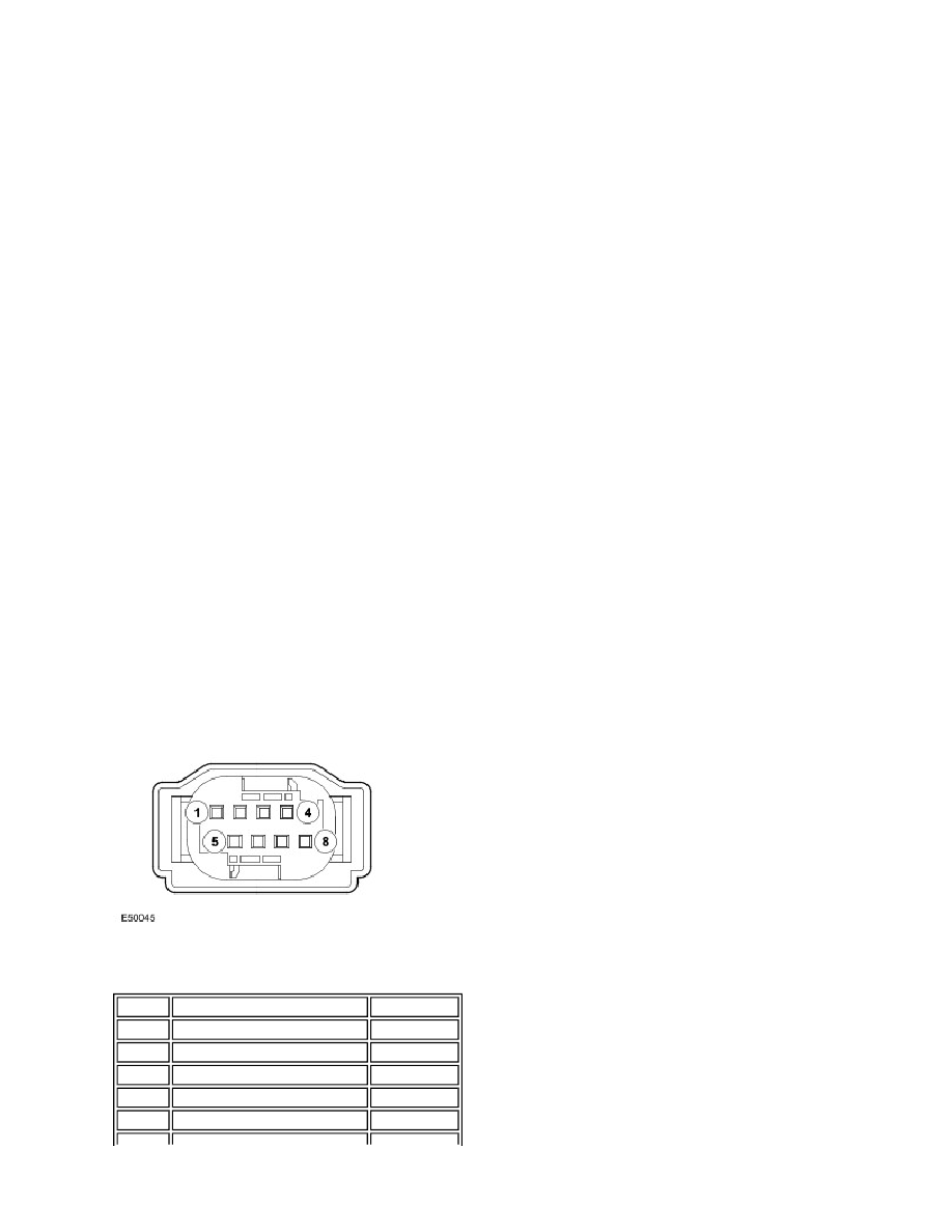
FFBH Control Module Harness Connector C0925
FFBH Control Module Harness Connector C0925 Pin Details
Pin No.
Description
Input/Output
1
Not used
-
2 and 3
Not used
-
4
Medium speed CAN bus low
Input/Output
5
Auxiliary fuel pump power feed
Output
6
Not used
-