
LR3/Disco 3
ACCM
The ACCM allows manual adjustment of the output from the auxiliary climate control assembly. The ACCM is installed in
the headliner immediately behind the row 2 interior lamp. An integral control panel contains separate rotary switches for
temperature, distribution and blower speed. When the ACCM is in manual mode, amber LED's in the switch surrounds
illuminate to indicate the current settings of the system and function symbols in the switch surrounds are illuminated when
the side lamps or headlamps are on.
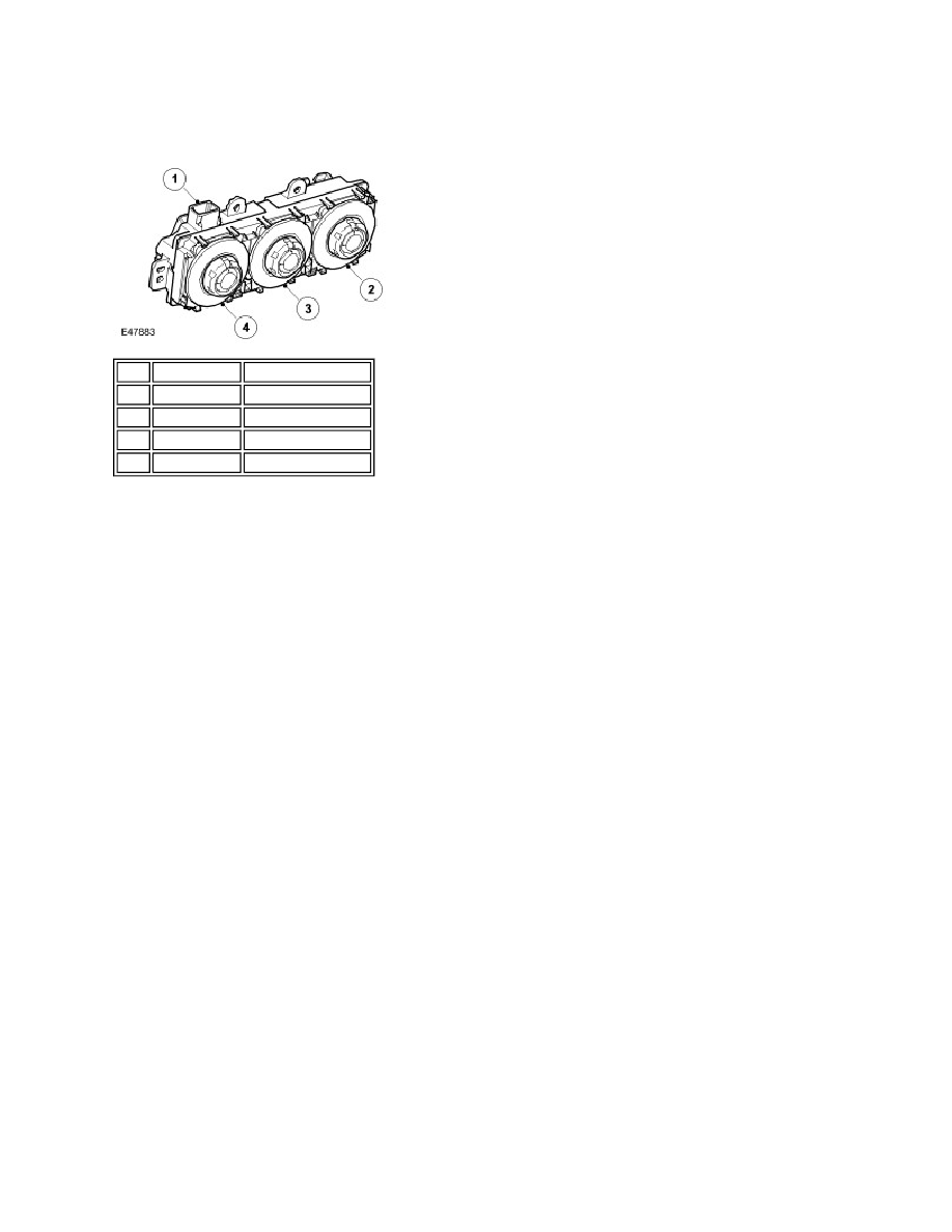
Details of the switches on the ACCM control panel are as follows:
Temperature Switch: The switch can rotate through 240°, from full cold to full hot. Minor detents allow fine
adjustment of the switch.
Distribution Control Switch: The switch can rotate through 120°. 5 primary detents define the distribution
settings of: Feet only; 3 face/feet; face only.
Blower Switch: The switch can rotate through 240°, from off to maximum speed. Eight primary detents define the
off position and seven blower speeds.
The ACCM is disabled when the auxiliary climate control switch on the ATCM is selected off. When the auxiliary climate
control switch is selected to automatic or manual, the ACCM is enabled by the connection of a power feed from the
ATCM. The same power feed also supplies the stepper motors in the auxiliary climate control assembly.
When it is enabled, the ACCM operates as a slave unit to the ATCM. The ACCM sends status signals on the LIN bus to
the ATCM, which replies with command signals of the required temperature, distribution and blower settings. The ACCM
then outputs the necessary drive signals to the auxiliary climate control assembly.
In the automatic mode, the command signals are derived from the comfort strategy in the ATCM. The temperature
setting is calculated from the mean of the two temperature settings on the ATCM.
In the manual mode, the command signals reflect the temperature, distribution and blower speed set by the
switches on the ACCM control panel. Temperature control by the auxiliary climate control system may be
compromised if the temperature settings on the ATCM are set to maximum hot or cold.
ACCM Harness Connector C0695
Item Part Number
Description
1
-
Electrical connector
2
-
Blower switch
3
-
Distribution switch
4
-
Temperature switch