
LR3/Disco 3
Connector C0958
Inputs and Outputs
Three connectors on vehicles with front and rear sensors and two connectors on vehicles with rear sensors only provide
the interface between the parking aid module and the external parking aid components.
The module receives inputs from the following:
Reverse selected - CAN message from transmission control module (automatic transmission) or transfer box
control module (manual transmission)
Forward gear selected (not in reverse or neutral) - CAN message from transmission control module (automatic
transmission) or transfer box control module (manual transmission)
Parking aid switch
Parking brake applied - CAN message
Trailer fitted - CAN message for central junction box
Ignition switch - Power supply
The module outputs signals to the following:
Sensors - power and ground connections
Sensors - digital signal - transmit and receive signals
Rear sounder - varying frequency output
Front sounder - CAN message to instrument cluster
Parking aid switch - power supply for switch LED operation
Controller Area Network (CAN) Signals
The parking aid module sends and receives a number of digital signals via the medium speed CAN. The received signals
are used for operation of the parking aid system.
The parking aid module receives the messages shown in the following table which are used to control the parking aid
system.
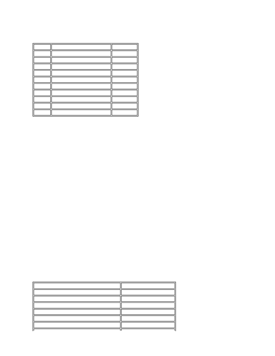
Pin No.
Description
Input/Output
1
Not used
-
2
Sensor signal - rear inner right
Input
3
Sensor signal - rear inner left
Input
4
Sensor signal - rear outer right
Input
5
Sensor signal - rear outer left
Input
6 and 7
Not used
-
8
Ground - rear sensors
Input
9 and 10
Not used
-
11
12V power supply - rear sensors
Output
12
Not used
-
Message
Transmitted by
Vehicle speed
ABS module
Selected gear position - Automatic transmission Transmission control module
Selected gear position - Manual transmission
Transfer case control module
Electric park brake on/off
Electric park brake module
Vehicle movement status
ABS module
Trailer connected
Central junction box