
LR3/Disco 3
Steering angle - from steering angle sensor
Vehicle speed - from ABS module
Low beam status - from instrument cluster
Suspension height - from air suspension control module
Odometer value - for diagnostics only
Engine running - from ECM
Gear position - From transmission control module or transfer box control module
Engine crank - from ECM
Exterior/interior temperature - for diagnostics only.
The AFS will only operate when the AFS control module receives an engine running signal on the CAN bus. When the
engine running signal is received and the lighting control switch is in the headlamps position, the AFS control module
performs an initialisation routine.
The AFS will also function when the lighting control switch is in the AUTO position and the AFS control module receives a
lights on signal from the rain/light sensor and an engine running signal.
The AFS control module then monitors the inputs from the other vehicle systems to control the AFS functionality
according to cornering angles and vehicle speed.
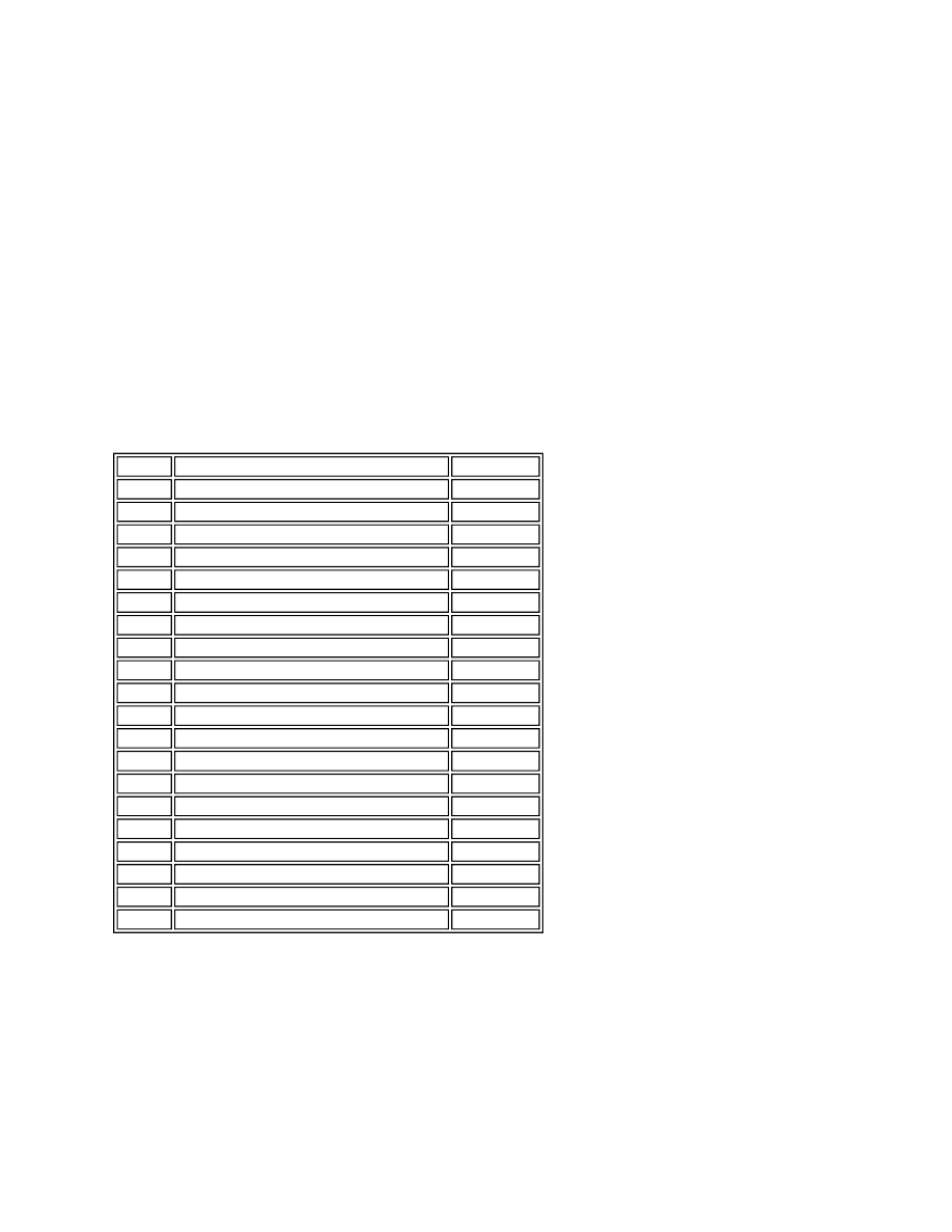
AFS Control Module Connector C2193 Pin Details
Operating Modes
The AFS has three modes of operation:
Manoeuvring mode
Normal driving mode
High speed mode
Reverse mode.
Manoeuvring mode is used for speeds up to 18.6 mph (30 km/h). Manoeuvring mode only moves the xenon projector
Pin No.
Description
Input/Output
1
Ground
Input
2 and 3
Not used
-
4
CAN High
Input/Output
5
CAN Low
Input/Output
6
RH Headlamp swivel actuator signal
Output
7
RH Headlamp swivel actuator signal
Output
8
Not used
-
9
RH Headlamp levelling motor 1 - Positive +
Output
10
RH Headlamp levelling motor 1 - Negative -
Input
11
RH Headlamp levelling motor 2 - Positive +
Output
12
RH Headlamp levelling motor 2 - Negative -
Input
13
12V Ignition feed
Input
14 to 17
Not used
-
18
LH Headlamp swivel actuator signal
Output
19
LH Headlamp swivel actuator signal
Output
20
Not used
-
21
LH Headlamp levelling motor 1 - Positive +
Output
22
LH Headlamp levelling motor 1 - Negative -
Input
23
LH Headlamp levelling motor 2 - Positive +
Output
24
LH Headlamp levelling motor 2 - Negative -
Input