
LR3/Disco 3
Vehicle height information from air suspension control module.
When the ignition switch is in the ignition position (II), power is supplied to the lighting control switch via the ignition relay
in the Battery Junction Box (BJB) and to the AFS control module. When the lighting control rotary switch is moved to the
side lamp or headlamp position, the supply from the ignition relay is passed to the AFS control module.
NOTE :
The system operates by the AFS control module receiving inputs on the CAN from the air suspension control module for
front and rear vehicle height, from the engine control module for engine running signal and from the ABS module for stop
lamp switch active (brakes applied) and vehicle speed. The AFS control module processes these signals and provides an
output to the headlamp levelling motors to adjust the headlamp vertical aim according to vehicle speed and attitude.
NOTE :
DAYTIME RUNNING LAMPS (DRL)
For additional information, refer to
Daytime Running Lamps (DRL)
(417-04 Daytime Running Lamps (DRL))
FRONT FOG LAMP (If Fitted)
Front fog lamps are an optional fitment on low specification vehicles and a standard fitment on high specification vehicles.
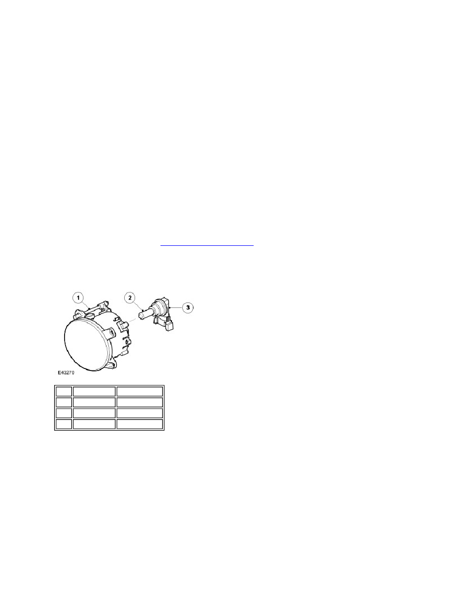
Two front fog lamps are located in apertures in the front bumper. Each lamp is secured in the bumper with three screws
which are covered with a finisher. The fog lamp has an adjuster screw which is accessible by removal of the lamp
surround and is used to set the fog lamp to the correct alignment.
The fog lamp uses a 55W halogen H11 bulb which is located in a holder. The holder is located in a hole in the rear of the
fog lamp housing and is turned to lock in position.
The front fog lamps are controlled by the lighting control switch. When the ignition switch is in the ignition position (II) and
the lighting control switch is in the side lamp or headlamp position, the lighting control switch can be pulled to the first
position to activate the front fog lamps.
If the switch is pulled to the second position, the front and rear fog lamps are activated. A front fog lamp warning indicator
When the AFS control module receives an ignition on signal, the control module performs an initialisation
procedure for both the AFS and headlamp levelling motors. Refer to the previous AFS section for details of the
initialisation procedure.
In markets with Daytime Running Lamps (DRL), the dynamic headlamp levelling system will not operate when the
DRL are active.
Item Part Number Description
1
-
Adjuster screw
2
-
Halogen bulb
3
-
Bulb holder