
LR3/Disco 3
Headlamps
Principles of Operation
This section details diagnostic information for the Adaptive Front Lighting System (AFS). For more details on system
operation,
Exterior Lighting
Inspection and Verification
1 . Verify the customer concern.
2 . Visually inspect for obvious signs of mechanical or electrical damage.
3 . If an obvious cause for an observed or reported concern is found, correct the cause (if possible) before proceeding to
the next step
4 . If the cause is not visually evident, verify the symptom and refer to the Symptom Chart.
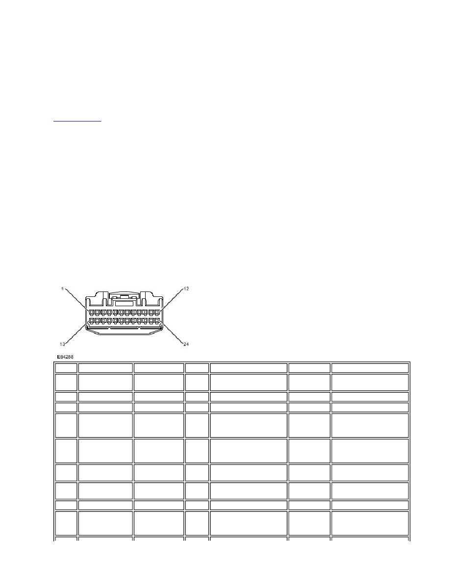
Connector Circuit Reference
AFS Control Module - C2193
Published : Jul 14, 2005
Cavity
Description
DTC
PID
Symptom
Input/Output
Possible Cause
1
Ground
None
None
No AFS operation
Input
Open circuit or short
circuit to battery voltage
2
Cavity not used
n/a
n/a
n/a
n/a
n/a
3
Cavity not used
n/a
n/a
n/a
n/a
n/a
4
High speed CAN
bus - High
U1A1413 ,
U007311,
U030088
None
Swivel and level
functions set to default
position - straight ahead
Input/Output
Open circuit , short circuit
to ground, short circuit to
battery voltage
5
High speed CAN
bus - Low
U1A1413 ,
U007311,
U030088
None
Swivel and level
functions set to default
position - straight ahead
Input/Output
Open circuit , short circuit
to ground, short circuit to
battery voltage
6
RH swivel motor
ground
U1A3913,
B1D6513
7103,
7104
No swivel operation
Input
Open circuit
7
RH swivel motor
signal
U1A3913,
B1D6511
7103,
7104
No swivel operation
Input/Output
Open circuit, short circuit
to ground
8
Cavity not used
n/a
n/a
n/a
n/a
n/a
9
RH levelling
motor 1 - Positive
B1A5813,
B1A5811,
B1A5888
7109,
710A
No levelling operation
Output
Open circuit, short circuit
to ground, short circuit to
battery voltage