
LR3/Disco 3
Foldback
Exterior mirrors with the foldback feature incorporate a foldback motor in the hinge of each exterior mirror. Operation of
the foldback motor is controlled by the exterior mirror control switch and the foldback module.
The foldback module is installed immediately outboard of the CJB, and controls power and ground connections to the
foldback motors.
When the exterior mirror control switch is in the center (off) position, tilting the switch down connects a ground to the
foldback module. When it senses the ground signal for the first time, the foldback module connects a power supply and a
ground to the foldback motors to turn the exterior mirrors inwards. Tilting the switch down again causes the foldback
module to reverse the polarity of the connections to the foldback motors, and the motors turn the exterior mirrors
outwards. If the switch is operated while the exterior mirrors are moving, they stop and reverse direction until they reach
their original position. If one of the exterior mirrors has been manually folded, they can be re-synchronized by an inward
and outward operating cycle.
To prevent the foldback motors from overheating, the foldback function is disabled for 3 minutes if the mirror foldback
function is selected ten times within 60 seconds. On the tenth selection within 60 seconds, the exterior mirrors will only
unfold; if the selection is for the exterior mirrors to fold, the selection is ignored.
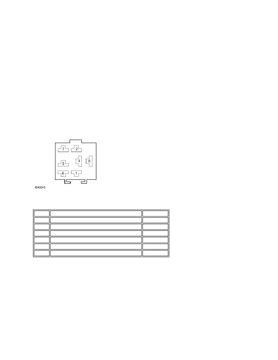
Foldback Module Harness Connector C0907
Foldback Module Harness Connector C0907 Pin Details
REAR VIEW MIRRORS CONTROL DIAGRAM (NON MEMORY)
NOTE :
Pin No.
Description
Input/Output
1
Foldback motor positive/negative
Input/Output
2
Foldback signal from exterior mirror control switch
Input
3
Foldback motor positive/negative
Input/Output
4
Power supply from fuse 16 of CJB
Input
5
System ground
Output
6 and 7
Not used
-
A = Hardwired connection; N = Medium speed CAN bus