
LR3/Disco 3
Should any of the passenger windows have opposing up/down requests from two separate switches, for example, the
drivers door switch and the switch on the operating window, then the operation of that window will cease, until one or both
of the switches are released.
System Inputs and Outputs
IGNITION SWITCH
The window lift system is enabled during ignition switch positions I and II, but disabled during cranking.
T4 can be used to monitor the state of the ignition switch.
WINDOW SWITCHES
Individual window switches are installed in each of the three passenger doors. Window switches for all of the windows,
are installed in the drivers door in the top surface of the door trim.
All window switches are of the non-latching rocker type and contain illumination bulbs that operate when the side lamps or
headlamps are on.
The drivers window switch has two switching positions in each direction, inch up/down and one-shot up/down. Operating
the switch to the second detent position will activate the one-shot feature. All the passenger windows have conventional
power motors, providing an inch up/down operation whilst the corresponding switch is held.
When the switches in the drivers door are used to operate the passenger windows or to isolate the rear windows, the
drivers door switch pack outputs a signal to the relevant window regulator. While the isolator is engaged, the rear
regulators ignore inputs from the rear window switches, and the drivers door switch pack illuminates a LED in the isolator
switch.
With the switches in the rest position, there is battery voltage at both sides of each switch as well as at the window
motors. Operating any switch provides a ground path through the switch to the window motor. Operating the switch in the
opposite direction switches the voltage path and the earth path to the motor allowing the motor to run in the opposite
direction.
Power for window operation is supplied from the window lift relay located in the CJB. When energised, the window lift
relay provides feed to the following fuses, which are also located in the CJB:
30 (25 Amps)
17 (20 Amps)
31 (20 Amps).
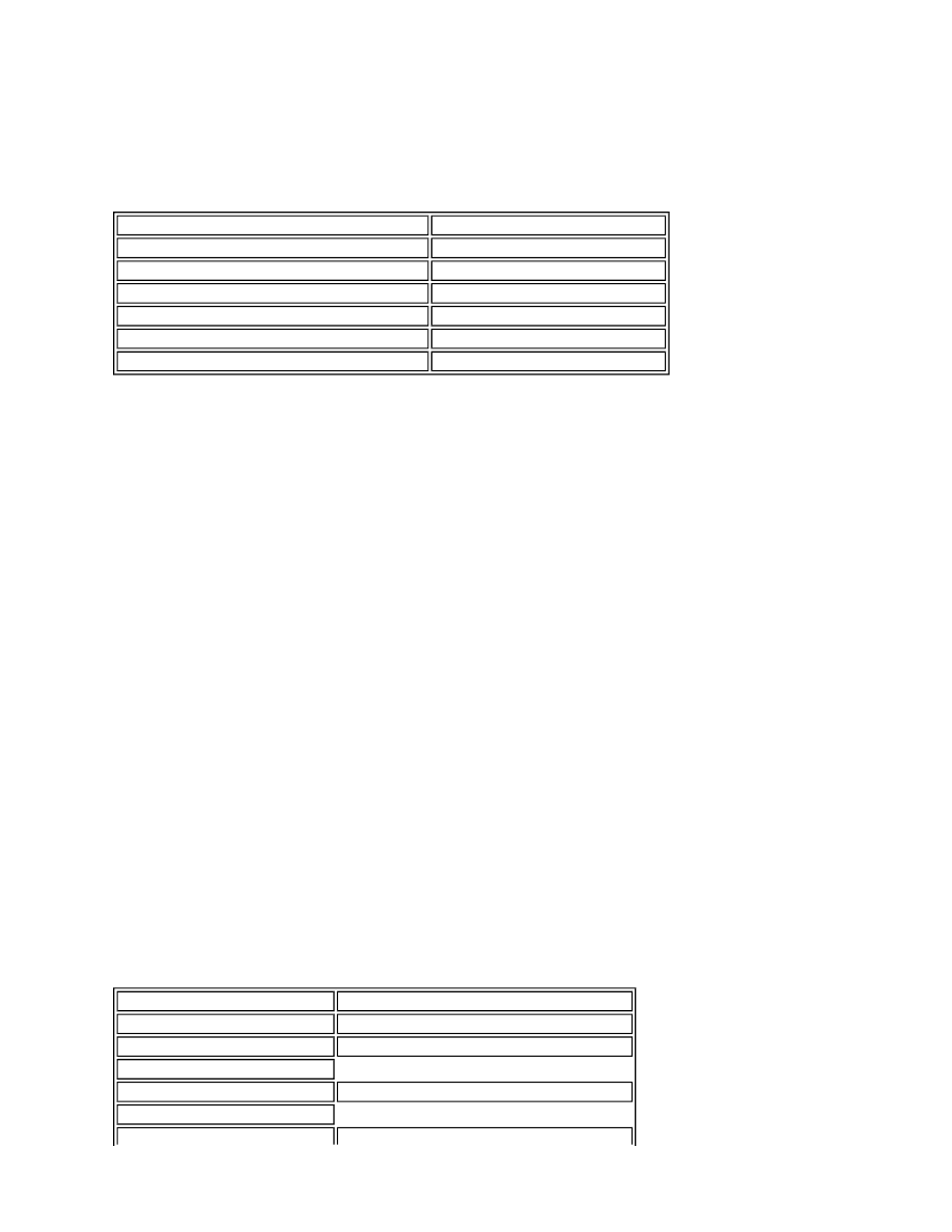
Inputs
Outputs
Ignition switch
CJB window enable signal
Drivers door switch pack
CJB window power feeds
Front passenger door window switch
Front window lift motors (LH and RH)
Rear passenger door window switch (LH and RH) Rear window lift motors (LH and RH)
Drivers door ajar switch
-
Front passenger door ajar switch
-
Fuse
Description
Fuse 7
Drivers window regulator
Fuse 17
Drivers switch pack, RH rear - up/down
RH rear window switch via isolator
Fuse 30
Drivers switch pack, front passenger - up/down
Front passenger switch - up/down