
LR3/Disco 3
When the on/off switch is selected on, the LED in the switch illuminates and power is supplied to the thermoelectric
cooler. The couples in the thermoelectric cooler then transfer heat from the liner of the cool box to the heatsink, and the
fan runs to cool the heatsink.
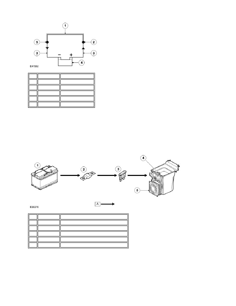
CONTROL DIAGRAM
Item Part Number
Description
1
Conductor material A
2
Hot junction
3
Conductor material B
4
Battery
5
Cold junction
Item Part Number
Description
1
Battery
2
Fusible link 18E, battery junction box (BJB)
3
Fuse 59P, CJB
4
Cool box on/off switch
5
Thermoelectric cooler