
Range Rover P38
EMISSION CONTROL
7
DESCRIPTION AND OPERATION
Crankcase ventilation system - from 99MY
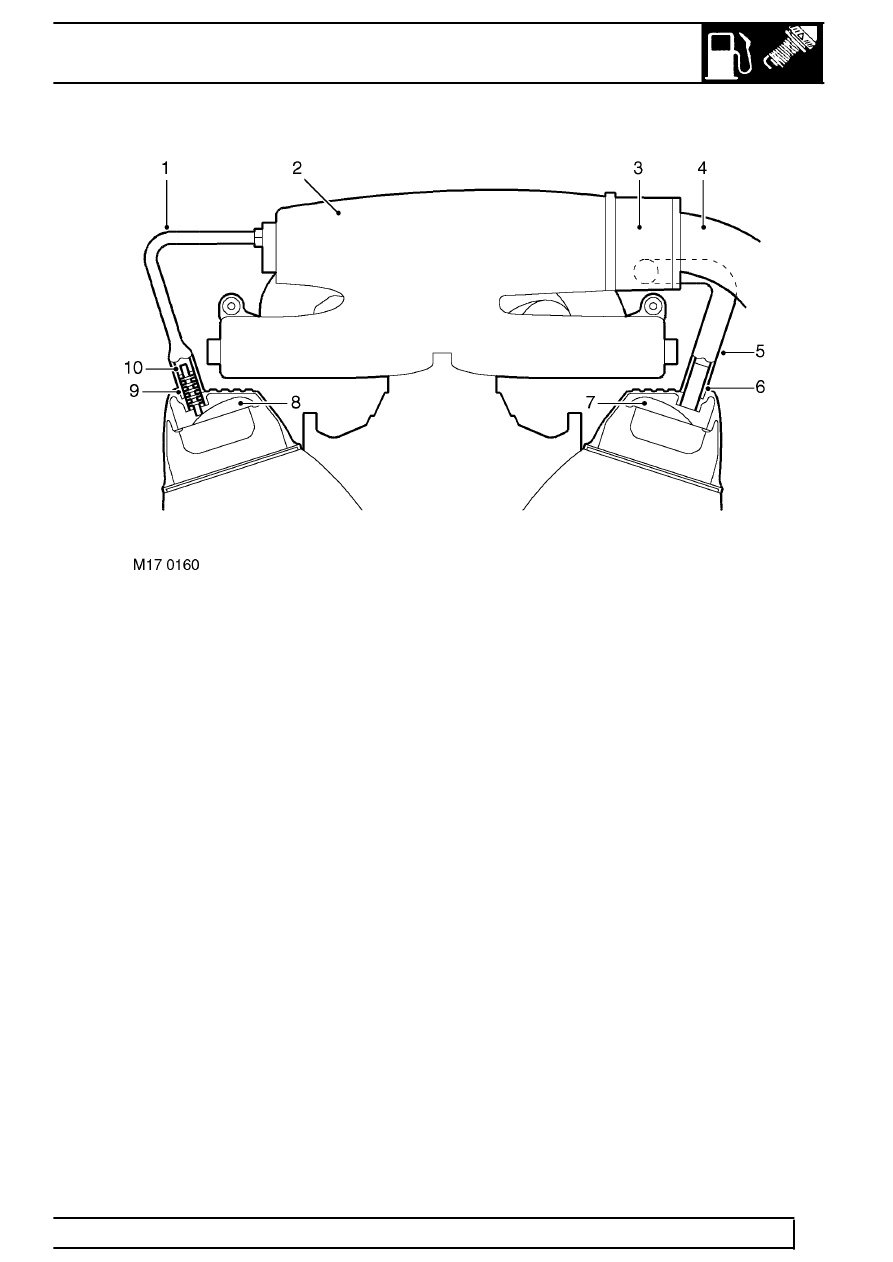
1. Hose - RH rocker cover to inlet manifold
2. Inlet manifold
3. Throttle body
4. Air intake
5. Hose - LH rocker cover to inlet manifold
6. LH rocker cover breather tube (without oil separator)
7. LH rocker cover baffle
8. RH rocker cover baffle
9. RH rocker cover breather tube
10. Oil separator (integral with breather tube)
A spiral oil separator is located in the stub pipe to the
ventilation hose on the right hand cylinder rocker
cover, where oil is separated and returned to the
cylinder head. The rubber ventilation hose from the
right hand rocker cover is routed to a port on the right
hand side of the inlet manifold plenum chamber,
where the returned gases mix with the fresh inlet air
passing through the throttle butterfly valve. The stub
pipe on the left hand rocker cover does not contain an
oil separator, and the ventilation hose is routed to the
throttle body housing at the air inlet side of the
butterfly valve. The ventilation hoses are attached to
the stub pipe by metal band clamps.
Oil laden noxious gas in the engine crankcase is
drawn through the spiral oil separator. The mass of
fresh air which is drawn in from the atmospheric side
of the throttle butterfly to mix with the returned
crankcase gas depends on the throttle position and
the engine speed.