
Range Rover P38
EMISSION CONTROL
1
FAULT DIAGNOSIS
TESTING EVAPORATIVE EMISSION CONTROL -
PRE ADVANCED EVAPS
The following pressure test procedure is intended to
provide a method for ensuring that the system does
not leak excessively and will effectively control
evaporative emissions.
Equipment required.
Nitrogen cylinder (compressed air may be used to
pressure the system when there has NEVER been
fuel present in the fuel or evaporative control
systems).
Water manometer 0 - 100 cm (0 - 30" H2O or more).
Pipework and a "T" piece.
Method.
1. Ensure that there is at least two gallons of fuel in
the petrol tank unless there has never been any
fuel in the system.
2. Disconnect, at the EVAP canister, the pipe to the
fuel tank vapour separator.
3. Connect this pipe to the nitrogen cylinder and
the water manometer using the "T" piece.
4. Pressurize the system to between 67.3 and 70.0
cm (26.5 and 27.5 inches) of water, allow the
reading to stabilize, then turn off the nitrogen
supply.
5. Measure the pressure drop within a period of 2
minutes 30 seconds. If the drop is greater than
6.3 cm (2.5 inches) of water the system has
failed the test. Note that a fully sealed system
will show a slight increase in pressure.
6. Should the system fail the test, maintain the
pressure in the system and apply a soap
solution round all the joints and connections until
bubbles appear to reveal the source of the leak.
7. Repeat the test and if successful, dismantle the
test equipment and reconnect the pipe to the
EVAP canister.
LEAK DETECTION PROCEDURE - ADVANCED
EVAPS
1. Connect TestBook to the vehicle and confirm
that the fault code(s) displayed relate to an
EVAP system fault.
2. Examine components in fuel and EVAP system
for damage or poorly connected joints.
3. Repair or replace components to rectify any
faults found, then reset the Malfunction Indicator
Lamp (MIL) using TestBook.
4. Carry out Drive Cycle,
See this section.
5. Using TestBook confirm that the Evaporative
Loss Control (ELC) Inspection and Maintenance
(IM) flag has cleared. This procedure should
confirm that the ELC test was carried out during
the drive cycle and that the fault was cured.
6. If the IM flag is still shown, use TestBook to
interrogate the engine management system to
ascertain which of the following situations exists:
•
If a fault code is shown, then further investigation
is required, proceed to the next step.
•
If the IM flag is still shown, but no faults are
indicated the conditions for the ELC check have
not been met and the drive cycle must be
repeated.
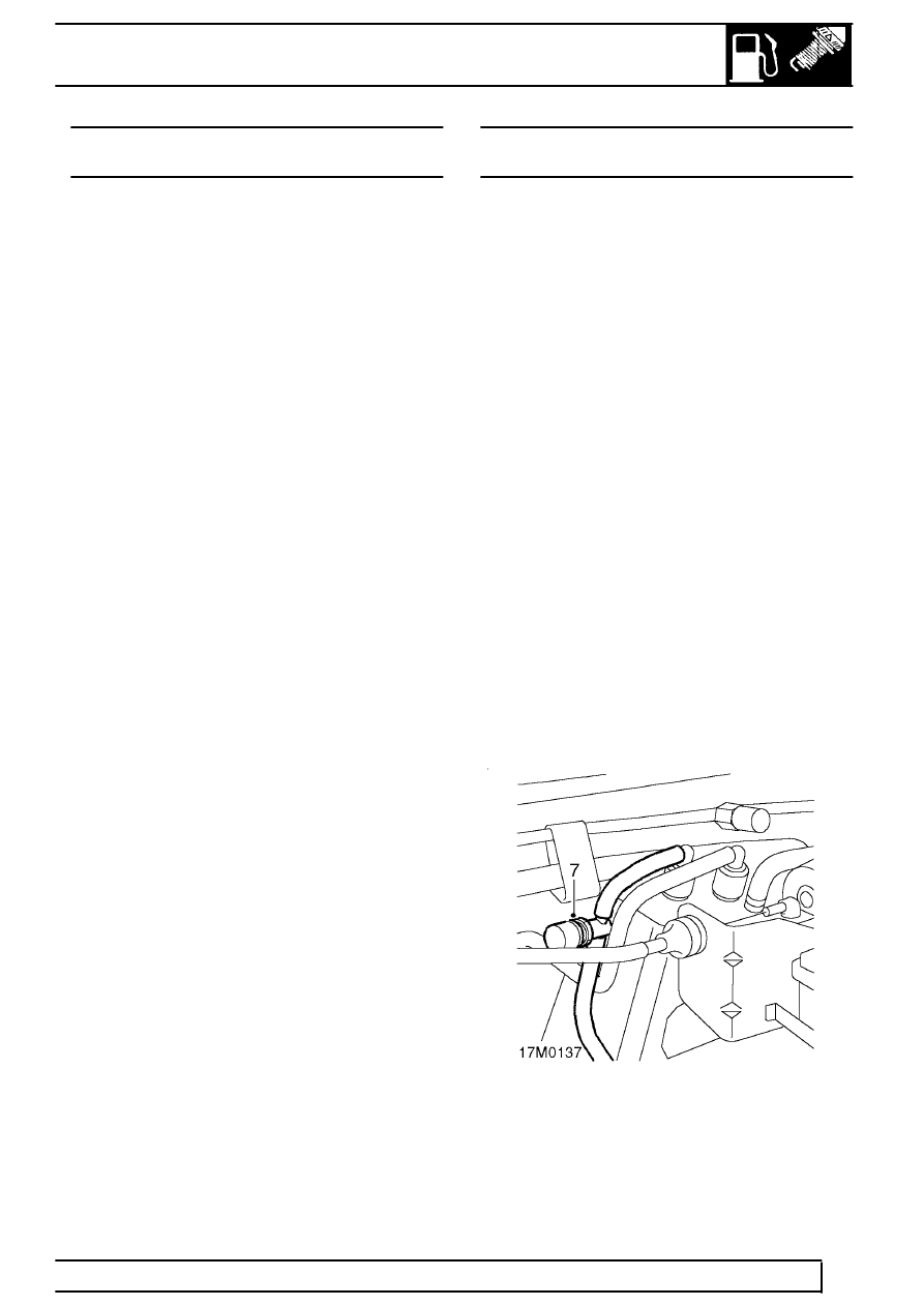
7. Connect the EVAP Diagnostic Station to the
service port and carry out the procedures given
in the operating instructions supplied with the
equipment.
8. Rectify faults indicated by the EVAP Diagnostic
Station and return to step 4.