
Range Rover P38
19
FUEL SYSTEM
NEW RANGE ROVER
8
DESCRIPTION AND OPERATION
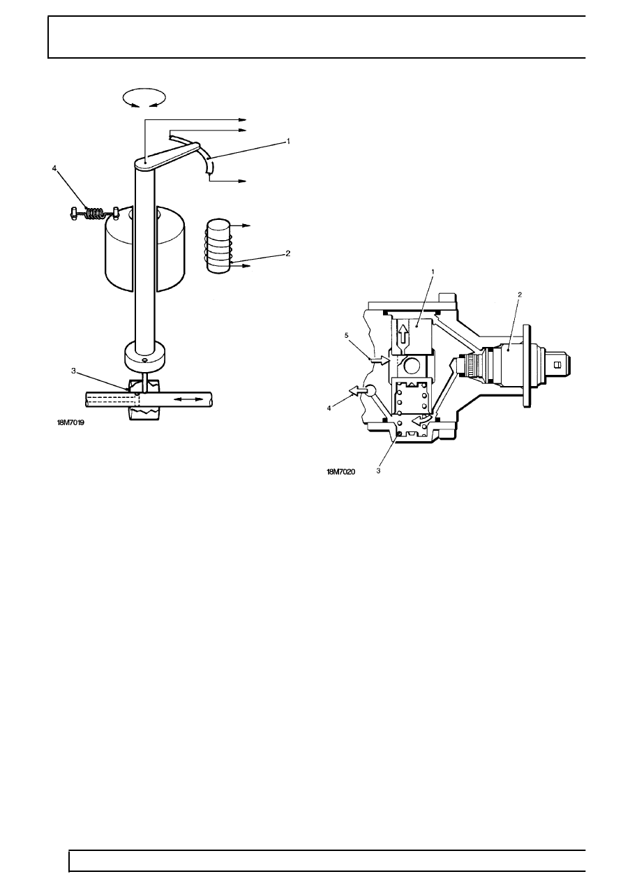
1. Rotary potentiometer
2. Control coil
3. Control spool
4. Return spring
When the control coil is energised the rotary magnet
and eccentric shaft move against spring pressure.
Rotary movement of the eccentric shaft is converted
into linear movement of the control spool. This allows
more fuel to be delivered to the injectors.
When the control coil is de-energised the return spring
causes the rotary magnet and eccentric shaft to
resume their original position. The control spool is
moved to the zero position.
The control unit accurately controls the position of the
control spool to achieve the desired engine
performance.
Stop solenoid
This is a solenoid operated valve located on the high
pressure section of the injection pump. When the
ignition is switched ON it receives voltage supply and
the valve opens allowing fuel to flow.
When the ignition is switched OFF the valve closes
and the fuel supply is cut.
Injection timing device
This injection timing device is housed within the fuel
injection pump. It consists of a spring-loaded plunger
and a solenoid. The spring loaded plunger moves
under the influence of pump working pressure. The
solenoid is controlled by a pulsed frequency signal
from the control unit.
When the pump is operating the solenoid regulates
the speed dependent, internal pump pressure into
working pressure. This moves the plunger against
spring tension.
1. Plunger
2. Solenoid
3. Spring
4. Pump feed pressure
5. Pump internal pressure
Injection is retarded with an energised solenoid and
the resultant pressure drop. The beginning of injection
is advanced with a de-energised solenoid and the
resultant pressure rise.
Heater time relay
Glow plug preheating time is regulated by the heater
timer relay in the heating time control unit. This
connects to the glow plugs in the cylinder head and to
the ECM.
The control unit monitors and operates the glow plugs;
operating time for the glow plugs is dependent on
engine temperature.