
Range Rover P38
19
FUEL SYSTEM
NEW RANGE ROVER
16
DESCRIPTION AND OPERATION
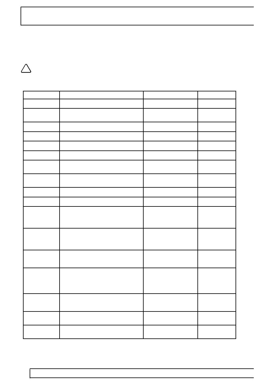
36-pin red connector (C507):
This connector is used primarily for sensor inputs to the ECM.
NOTE: Voltages and other measurements given are approximations only. Actual values will
depend on particular specification and will be affected by accuracy and calibration of the
measurement tool used and impedances caused by harness wiring etc.
ECM pin details for Connector C507:
Pin No.
Description
Input/Output
Voltage
1
Rough road detected
Input
0 -12V
2
Camshaft position (CMP) sensor
Input (2 pulses per
engine revolution)
12V (average)
3
Not used
-
-
4
Transfer box (Low range detected)
Input
0 - 12V
5
Not used
-
-
6
Not used
-
-
7
Fuel level
Input (out of range and
validity check only)
0 - 12V
8
HO
2
S Bank B Upstream
Input
0V (Rich) - 5V
(Lean)
9
Not used
-
-
10
Knock sensor ground
Ground
0V
11
Knock sensor A
Input
Voltage signal
proportional to
level of knock
detected
12
Knock sensor B
Input
Voltage signal
proportional to
level of knock
detected
13
Air temperature sensor
Input
1 k-ohm to 1.3
k-ohm at 40
°
C
(140
°
F)
14
Coolant temperature sensor
Input
4.7V at -30
°
C
(-22
°
F) to
0.25V at 130
°
C
(266
°
F); 2.0V
at 40
°
C (104
°
F)
15
Throttle position sensor
Input
0 to 5V (0.6V at
idle; 4.5V
typical max.)
16
Mass air flow (MAF) Sensor
Analogue input
0 to 5V (1.4V at
idle)
17
HO
2
S sensor Bank A Downstream
Input
0V (Rich) - 5V
(Lean)