
Range Rover P38
LAND ROVER V8
19
DESCRIPTION AND OPERATION
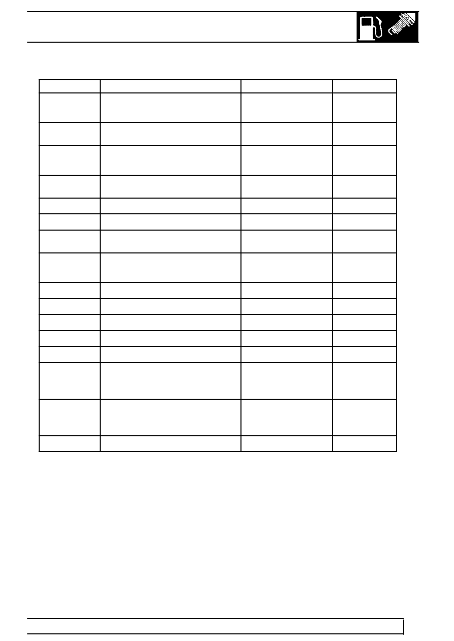
ECM pin details for Connector C505 continued:
Pin No.
Description
Input/Output
Voltage
21
HO
2
S sensor Upstream - Heater supply
Output
Heater
resistance =
5.7 ohms
22
Malfunction Indicator Lamp (MIL)
Output drive
Switch to
ground
23
Engine speed output
Output
12V square
wave (4 pulses
per revolution)
24
Fuel pump relay
Output drive
Switch to
ground
25
Not used
-
-
26
Not used
-
-
27
Throttle position
Analogue input
0 - 5V (1.4V at
idle)
28
HO
2
S sensor Upstream - Heater supply
Output
Heater
resistance =
5.7 ohms
29
Engine torque
Output
12V PWM
30
Injector - Cylinder 4
Output
0 - 12V
31
Not used
-
-
32
Injector - Cylinder 7
Output
0 - 12V
33
Injector - Cylinder 5
Output
0 - 12V
34
IACV-C Stepper motor
Output
stepped by
sequentially
changing
voltage polarity
35
IACV-A Stepper motor
Output
stepped by
sequentially
changing
voltage polarity
36
Injector - Cylinder 2
Output
0 - 12V