Range Rover P38

19
FUEL SYSTEM
NEW RANGE ROVER
40
DESCRIPTION AND OPERATION
Crankshaft speed and position (CKP) sensor -
(from 99MY)
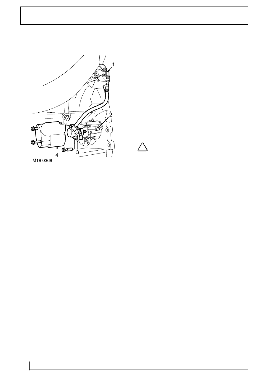
1. Multiplug
2. Aperture to reluctor ring
3. CKP sensor
4. Heatshield
The CKP sensor is located at the lower, rear LH side
of the engine below cylinder number 7. The CKP
sensor is protected by a heatshield which is attached
to the rear flange of the engine block by two M5 bolts.
The CKP sensor itself is located on two studs and
fixed in position by two M5 nuts and 18mm spacers.
The sensor has a flying lead which terminates in a
3-pin multiplug that connects to the engine harness
and is mounted to a bracket to the rear of the left hand
cylinder head.
The tip of the CKP sensor protrudes through an
aperture in the engine block rear flange, adjacent to
the outer circumference of the flywheel. A 60-tooth
reluctor ring is included on the flywheel which
provides the reference signal to the crankshaft
position sensor.
The ECM uses the signal produced at the CKP sensor
to determine the position of the crankshaft to enable
accurate ignition and fuel injection timing. The ECM
also determines the engine speed at any particular
instance through analysis of the frequency of
fluctuations induced in the CKP sensor as the teeth of
the reluctor ring pass by the sensor tip.
The CKP sensor is a variable reluctance sensor, and
contains a permanent magnet and soft iron core
surrounded by a copper winding. As the reluctor ring
passes by the sensor tip it causes a voltage to be
induced in the sensor, consequently the CKP sensor
does not need a power supply for operation. The
signal wires of the CKP sensor are surrounded by a
grounded screen to prevent noise being induced in
the signal wires and causing a spurious interference
signal being passed to the ECM.
NOTE: When fitting a CKP sensor, ensure
no ferrous metal has been attracted to it
by its magnet. Ensure the sensor pin is
straight and undamaged.
The reluctor ring teeth are spaced at 6
°
intervals and
are 3
°
wide. Two of the reluctor ring teeth are
removed, to provide a reference mark which indicates
when the crankshaft is at 60
°
BTDC for number 1
cylinder. The remaining 58 teeth cause an AC voltage
to be induced in the sensor pick-up, with the
amplitude of the signal increasing with rising engine
speed. The voltage generated is an analogue signal
capable of peak amplitude voltages of up to 300V.
The distance of the tip from the top of the reluctor ring
teeth is important as the amplitude of the detected
signal will be reduced in proportion to an increase in
the gap between the sensor tip and the top of the
reluctor ring teeth. If the air gap becomes too wide,
the CKP signal could become too weak and possible
misfires could occur. Spacers are included in the CKP
sensor kit which are used to ensure the correct gap
between the sensor tip and reluctor ring teeth.
The ECM uses the falling edge of the signal waveform
as its reference for each reluctor ring tooth.
Consequently, if the input signal wire and reference
ground wire are inadvertently reversed, the ECM will
react by providing a 3
°
advance in ignition timing.
