
Range Rover P38 - Coolant System - Land Rover V8 Engine Cooling
LAND ROVER V8
5
DESCRIPTION AND OPERATION
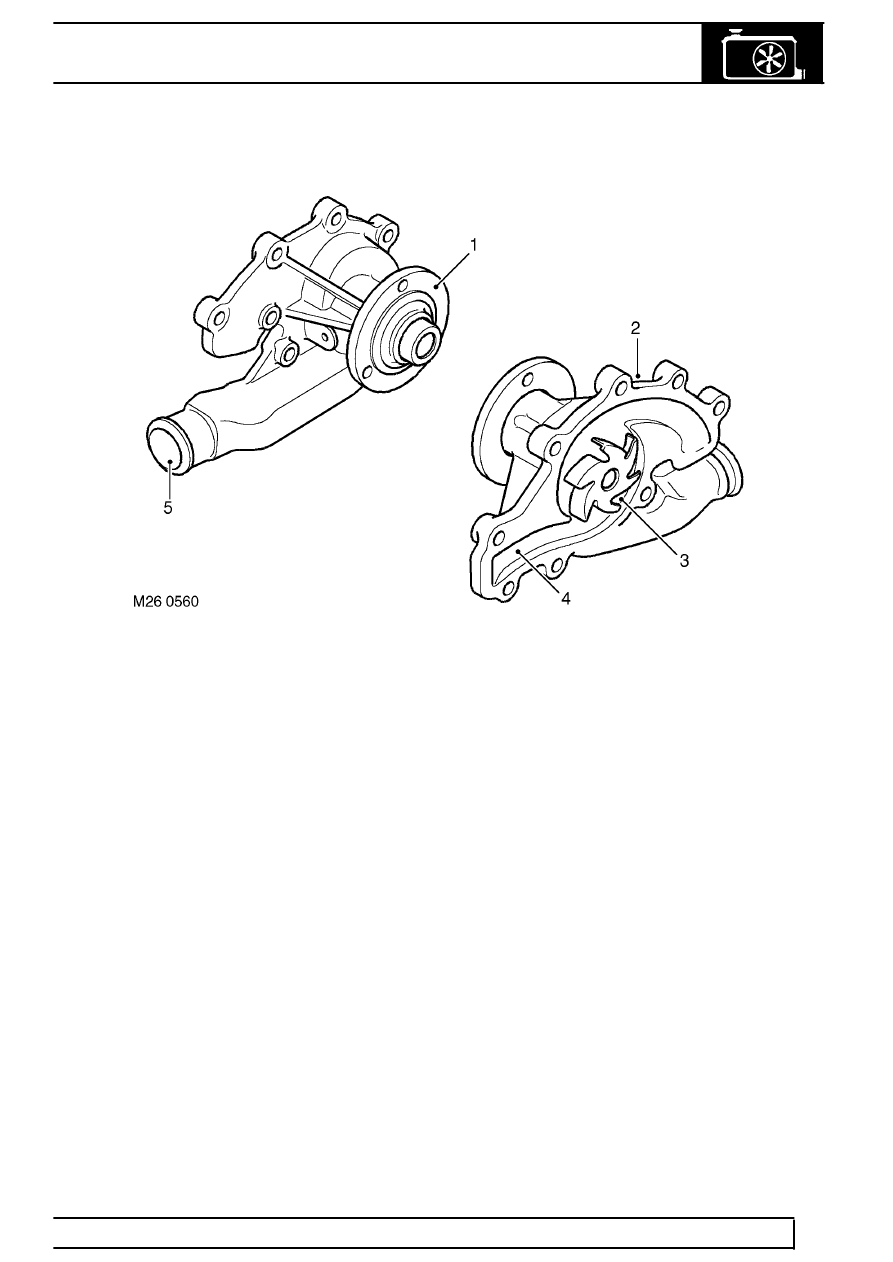
Coolant pump
1. Pulley flange
2. Body
3. Impeller
4. Gallery
5. Inlet connection
The coolant pump is attached to the front of the
cylinder block with nine bolts and sealed between the
pump housing and the cylinder block with a gasket.
The pump comprises a shaft which passes through an
alloy housing.
The outer end of the shaft has a flange which allows
for the attachment of the pump drive pulley which is
secured with three bolts. The drive pulley is driven by
the grooved auxiliary drive belt and rotates at the
same speed as the crankshaft. The inner end of the
shaft is fitted with an impeller which draws coolant
from the thermostat housing and circulates it through
galleries in the cylinder block and through the heater
matrix.
The shaft is supported on bearings in the housing
which are packed with grease and sealed for life. A
seal is positioned in the housing to further protect the
bearings from the ingress of coolant. The seal is
manufactured from a synthetic material which will
allow for the expansion of the casing when hot coolant
is present.
The cast alloy housing has a hose connection which
provides the attachment for the coolant pump feed
hose. The housing connects with galleries in the
cylinder block and distributes coolant from the pump
impeller into the galleries and water jackets.