
Range Rover P38
70
BRAKES
NEW RANGE ROVER
8
DESCRIPTION AND OPERATION
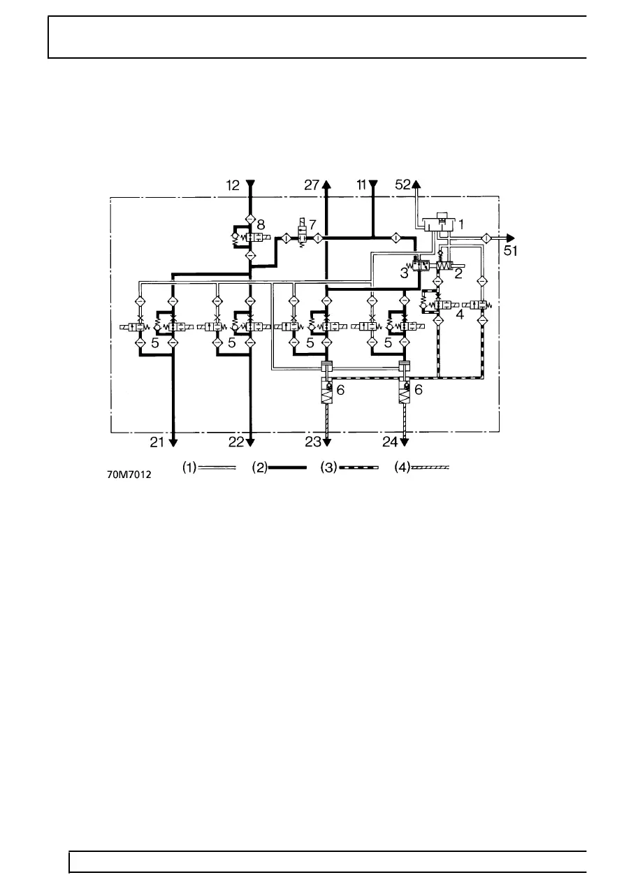
Hydraulic Circuit Diagram
Brake booster/ABS modulator unit - up to 99MY
(1) Fluid feed/return
(2) Power circuit
(3) Hydrostatic (master cylinder) circuit
(4) Combined hydrostatic/power circuit
Brake booster/ABS modulator unit components
1. Fluid reservoir
2. Master cylinder
3. Power valve
4. Isolating valve
5. ABS solenoid control valves
6. Servo cylinders
ETC option
7. ETC inlet solenoid valve - normally closed
8. ETC isolating solenoid valve - normally open
Brake booster/ABS modulator unit port
identification
11.
High pressure supply from hydraulic pump
12.
Supply from PCRV
21.
Supply to left hand rear caliper
22.
Supply to right hand rear caliper
23.
Supply to left hand front caliper
24.
Supply to right hand front caliper
27.
Supply to PCRV
51.
Low pressure supply to hydraulic pump
52.
Supply to clutch master cylinder (manual
vehicles)