Range Rover P38

SUPPLEMENTARY RESTRAINT SYSTEM
9
DESCRIPTION AND OPERATION
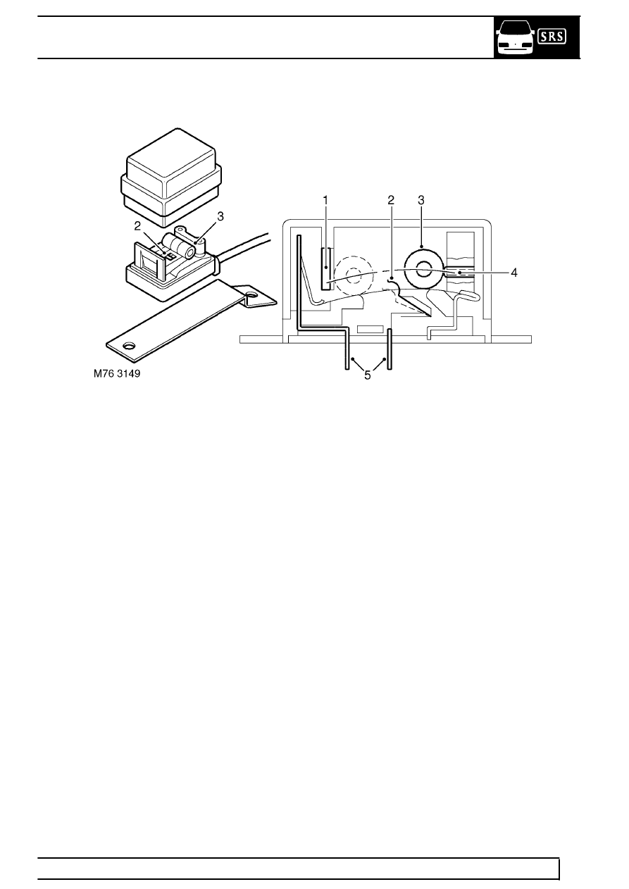
Front Crash Sensors (distributed systems only)
1. Roller stop
2. Contact spring
3. Weight roller
4. Stop screw in "off" position
5. Electrical connection
The front crash sensors are located behind each
headlamp in the engine compartment. The sensors
are provided in a yellow, plastic encapsulated housing
with an integral mounting bracket for attaching the
units to the vehicle body. A yellow 3-pin connector
connects each impact sensor to the main harness and
an additional 4-way orange connector interfaces
between the main harness and the fascia harness and
is located on the lower left hand ’A’ post. In the event
of a crash sensor fault being detected by the
diagnostics system, the connection between the
fascia and main harnesses should be checked.
The sensors must be fitted in the correct orientation;
an arrow is moulded into the upper surface of the
housing to indicate the end of the sensor which must
face the front of the vehicle. Each sensor is attached
to the vehicle body by two Torx bolts. It is important to
ensure the crash sensors are mounted correctly.
The internal components of the crash sensor consist
of a weighted roller with a spring contact around it.
Under deceleration, the roller unwinds the spring until
a contact is made to provide a short circuit input to the
DCU. This signal indicates that a rapid deceleration
has been detected such as that which would be
experienced during a frontal collision.
