
Range Rover P38
CHASSIS AND BODY
55
REPAIR
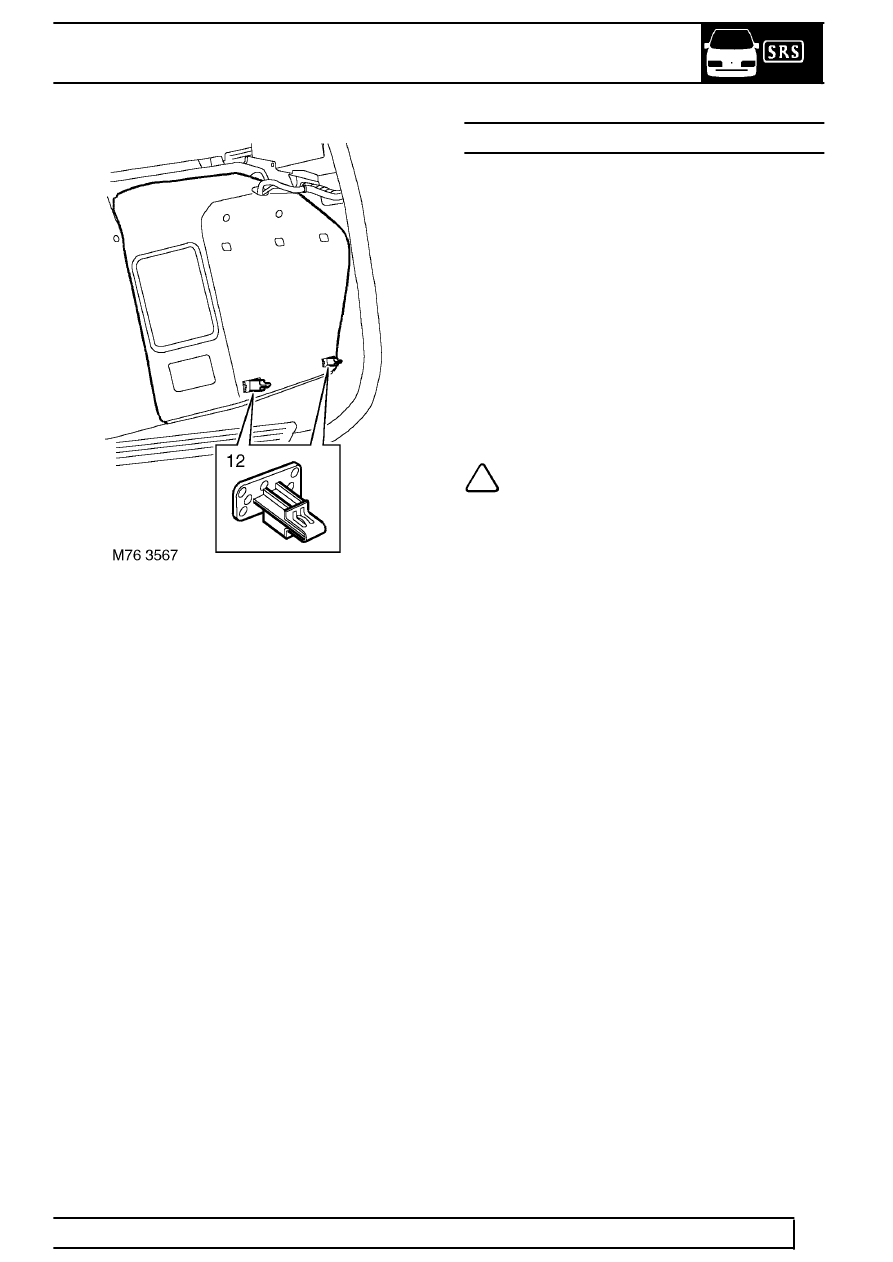
9. Release 2 clips securing trim to body and
remove trim.
Refit
10. Position trim panel to body and secure clips.
11. Fit mounting bracket to body with trim clips.
12. Feed satellite navigation and power socket wires
through correct holes, Push trim into place and
secure with trim clip.
13. Position mounting bracket behind trim and feed
mounted threads through holes in trim.
14. Position power socket bracket, feed wires
through bracket and connect socket.
15. Fit socket to bracket and secure clip and screw.
16. Position mounting plate to top of trim and
position GPS receiver to mounting plate.
17. Fit satellite navigation computer bracket to trim
and secure with nuts.
18. Fit satellite navigation trim cover and secure with
screws and trim clips.
19. Fit satellite navigation computer.
See
ELECTRICAL, Repair.
20. Fit parcel tray support.
See this section.
A,B,D and E POST TRIMS
Remove
1. Remove aperture seal from appropriate area.
2. Remove retaining screws (’A’ post lower trims)
3. Remove seat belt top mounting (’B’ and ’D’ post
upper trims)
4. Release retaining clips, remove finisher.
Refit
5. Position finisher, secure with retaining clips and
screws.
6. Fit seat belt top mounting. Tighten to
25 Nm.
(18lbf. ft)
7. Secure aperture seal.
NOTE: Illustration 76M 7128 shows the
fixing method for the A, B, D and E post
trim finishers.
1. A post upper
2. A post lower left hand
3. A post lower right hand
4. B post upper
5. B post lower
6. D post upper
7. D post lower
8. E post