
Range Rover P38
82
AIR CONDITIONING
NEW RANGE ROVER
20
DESCRIPTION AND OPERATION
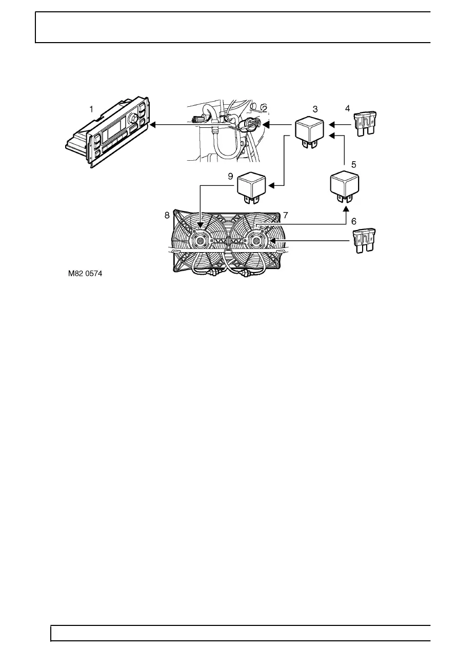
Condenser fans control diagram - slow speed
1. ATC ECU
2. Single pressure switch
3. Relay 18 (condenser fans control)
4. Fuse 37 (ignition power)
5. Relay 13 (LH condenser fan)
6. Fuse 31 (battery power)
7. LH condenser fan
8. RH condenser fan
9. Relay 14 (RH condenser fan)
Condenser fans control
The need to run the condenser fans, and the speed at
which they operate, is dependent on the pressure in
the refrigerant system, which in turn is dependent on
the amount of heat being extracted from the vehicle
interior and the ambient conditions.
When the ATC ECU energises the compressor clutch,
it simultaneously earths the line from the coil of the
condenser fans control relay. If refrigerant pressure is
sufficient to require operation of the condenser fans,
the contacts in the single pressure switch are closed,
and the condenser fans control relay energises. At
refrigerant pressures that require the condenser fans
to run at slow speed, the energised condenser fans
control relay connects the condenser fans in series,
via the LH and RH condenser fan relays, and the fans
run at slow speed.
If the refrigerant pressure increases to the upper limit
for slow speed operation of the condenser fans, the
fan speed contacts in the dual pressure switch close
and connect an earth to the coils of the LH and RH
condenser fan relays. The two condenser fan relays
then energise and connect the two condenser fans to
separate power supplies (i.e. in parallel) and the
condenser fans run at fast speed. If the refrigerant
pressure decreases to the lower limit for fast speed
operation, the fan speed contacts in the dual pressure
switch open, de-energise the condenser fan relays
and the condenser fans return to slow speed.