Assembling Output and Layshaft to Center Plate - R380 Gearbox Overhaul

MANUAL GEARBOX
OVERHAUL
35
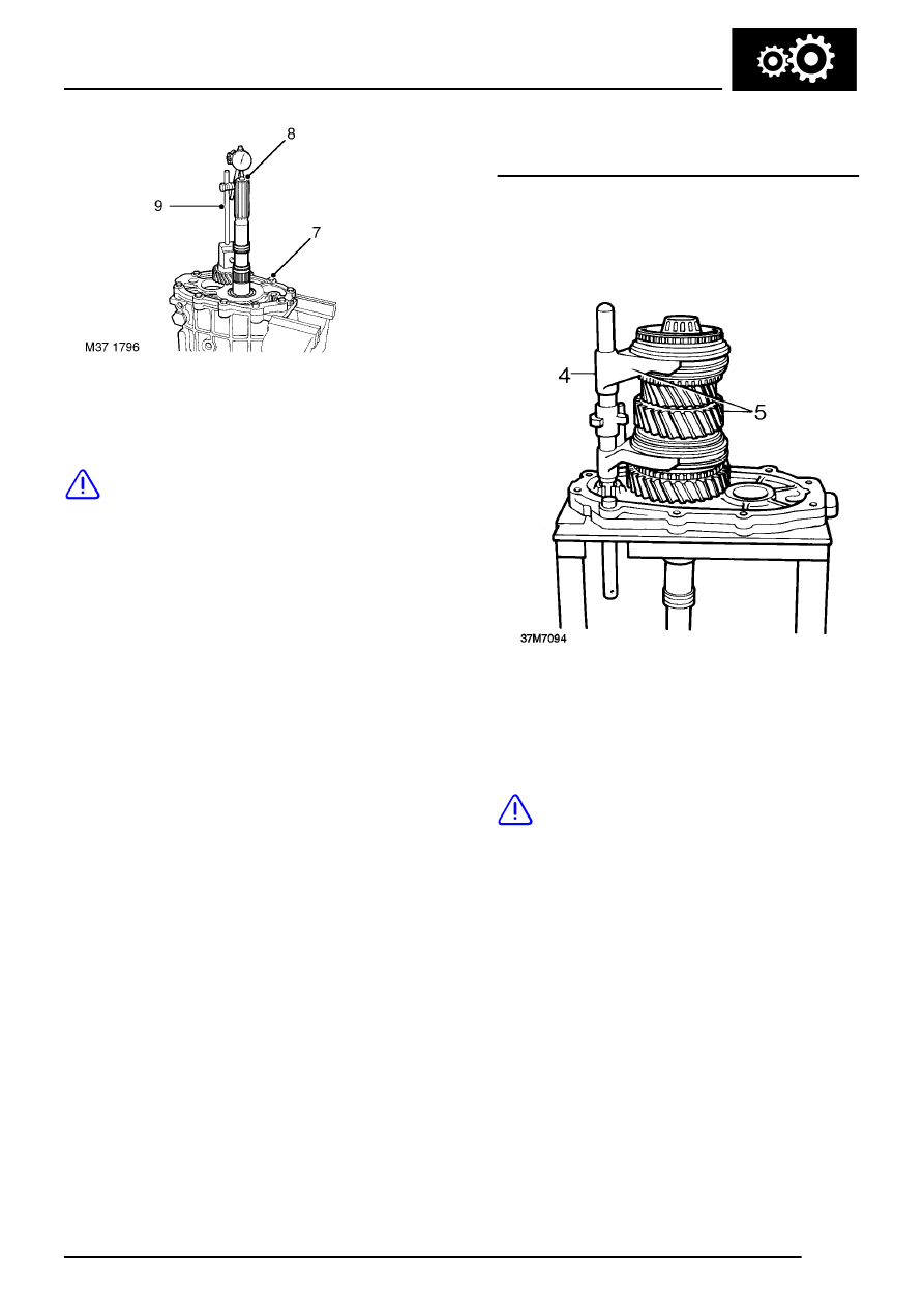
7. Fit centre plate and bolt down using 8 off 8 x
35 mm slave bolts.
CAUTION: Do not fit detent ball or spring
at this stage.
8. Fit large ball bearing to rear of output shaft.
9. Mount dial test indicator.
10. Rotate output shaft to settle bearings.
11. Lift output shaft and note DTI reading.
The end float setting for the output shaft and
layshaft is:-
Early gearboxes without suffix K added to serial
number:
New: 0.01 - 0.06 mm (0.0004 - 0.0024 in)
Service limit: 0.06 mm (0.0024 in)
Later gearboxes with suffix K added to serial
number:
New: 0.00 - 0.05 mm (0.00 - 0.002 in)
Service limit: 0.05 mm (0.002 in)
Shims to make up the required clearances are
placed under the respective bearing tracks in the
centre plate.
12. Dismantle and substitute shims if reading
incorrect.
13. Remove output shaft assembly and repeat
procedure for layshaft.
14. Remove centre plate, layshaft and output shaft.
15. Remove front cover.
16. Remove input shaft bearing track from front
cover, retain track with cover.
Assembling output shaft and layshaft to centre
plate
1. Secure centre plate to suitable workstand.
2. Fit selected shims and bearing tracks.
3. Fit lower detent ball and spring, use a dummy
bar to temporarily hold the ball in place.
4. Check both synchromesh units are in neutral
and fit selector shaft assembly to output shaft.
5. Fit output shaft and selectors as complete unit
to centre plate aligning pin with slot in plate.
CAUTION: Take care that as dummy shaft
is removed, detent spring and ball are not
displaced.
6. Fit 4th gear synchromesh baulk ring.
