
Ignition misfire (stumble) V8
- Make
- Land Rover
- Model
- Range Rover Classic Technical Bulletins
- Section
- Ignition misfire (stumble) V8 › Ignition misfire (stumble) V8
IGNITION MISFIRE (STUMBLE) V8
- Model
- Range Rover V8 Discovery V8
- Affected vehicles
- Range Rover from LH 651066 to LH 652331 Discovery from LJ 092968 to LJ 097888
- Date
- 1994-09-15
- Reference
- 15/09/94
Bulletin text
Ignition Misfire (Stumble)
MODEL AFFECTED VEHICLES
Range Rover V8 Range Rover from LH 651066 to LH 652331 Discovery V8 Discovery from LJ 092968 to LJ 097888
DETAIL
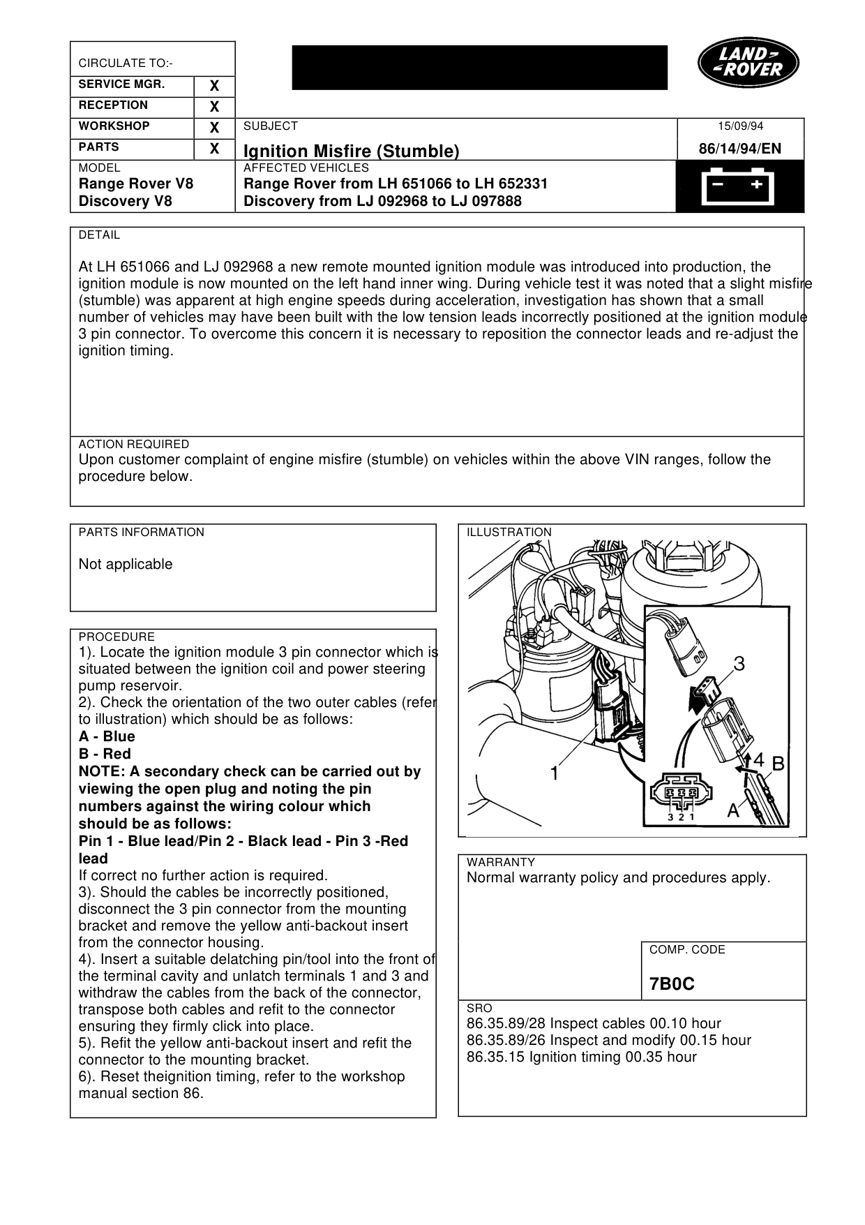
At LH 651066 and LJ 092968 a new remote mounted ignition module was introduced into production, the ignition module is now mounted on the left hand inner wing. During vehicle test it was noted that a slight misfire (stumble) was apparent at high engine speeds during acceleration, investigation has shown that a small number of vehicles may have been built with the low tension leads incorrectly positioned at the ignition module 3 pin connector. To overcome this concern it is necessary to reposition the connector leads and re-adjust the ignition timing.
ACTION REQUIRED
Upon customer complaint of engine misfire (stumble) on vehicles within the above VIN ranges, follow the procedure below.
PARTS INFORMATION
Not applicable
PROCEDURE
1). Locate the ignition module 3 pin connector which is situated between the ignition coil and power steering pump reservoir. 2). Check the orientation of the two outer cables (refer to illustration) which should be as follows: A - Blue B - Red NOTE: A secondary check can be carried out by viewing the open plug and noting the pin numbers against the wiring colour which should be as follows: Pin 1 - Blue lead/Pin 2 - Black lead - Pin 3 -Red lead If correct no further action is required. 3). Should the cables be incorrectly positioned, disconnect the 3 pin connector from the mounting bracket and remove the yellow anti-backout insert from the connector housing. 4). Insert a suitable delatching pin/tool into the front of the terminal cavity and unlatch terminals 1 and 3 and withdraw the cables from the back of the connector, transpose both cables and refit to the connector ensuring they firmly click into place. 5). Refit the yellow anti-backout insert and refit the connector to the mounting bracket. 6). Reset theignition timing, refer to the workshop manual section 86.
15/09/94
86/14/94/EN
WARRANTY
Normal warranty policy and procedures apply.
COMP. CODE
7B0C
SRO
86.35.89/28 Inspect cables 00.10 hour 86.35.89/26 Inspect and modify 00.15 hour 86.35.15 Ignition timing 00.35 hour
Parts & tools for this job For Land Rover Range Rover
- PARTEngine gasket setSearch: Land Rover Range Rover engine gasket set
- TOOLTorque wrenchSearch: 3/8 inch torque wrench
- TOOLFeeler gauge setSearch: feeler gauge set
Links open Amazon search results in a new tab. As an Amazon Associate I earn from qualifying purchases.