
ENGINE
- Make
- Land Rover
- Model
- Range Rover Classic
- Section
- REPAIR › ENGINE
12
ENGINE
12
REPAIR
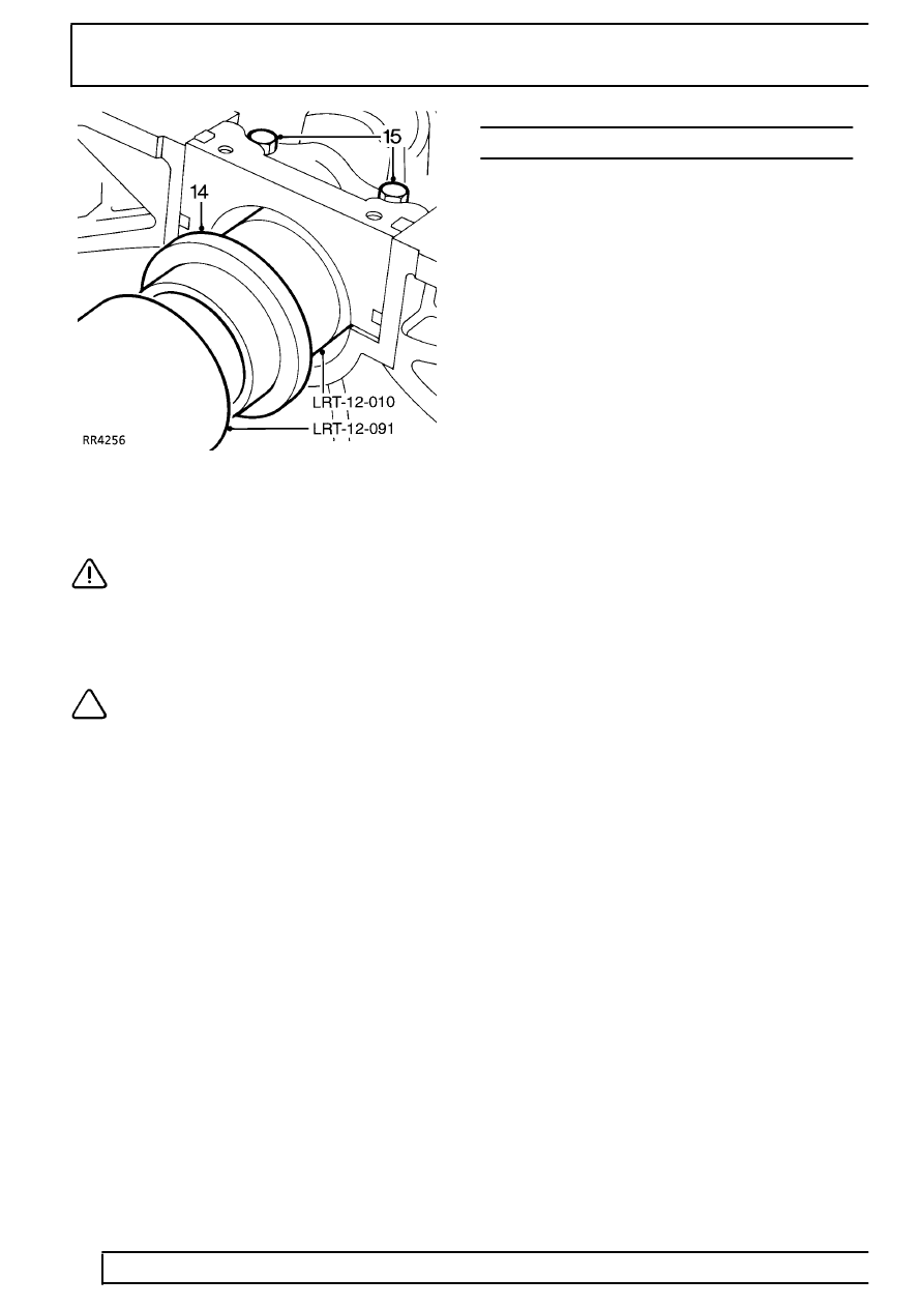
12. Ensure service tools LRT-12-010 and
LRT-12-091 are scrupulously clean. Coat seal
guide and oil seal journal with clean engine oil.
CAUTION: Do not handle oilseal lip, check
it is not damaged. Ensure outside diameter
remains clean and dry.
13. Position oil seal guide LRT-12-010 on crankshaft
flange.
NOTE: Lubricant coating must cover seal
guide outer surface completely to ensure
that oil seal lip is not turned back during
assembly. Position oil seal, lipped side towards
engine, on seal guide. Seal outside diameter
MUST be clean and dry.
14. Fit oil seal using tool LRT-12-091. Remove seal
guide.
15. Tighten rear main bearing cap to
90 Nm.
16. Fit sump.
17. Fit flywheel or flexible drive plate and ring gear.
ENGINE
Service repair no - 12.41.01
Remove
1. Park vehicle on level ground and apply park
brake.
2. De-pressurise fuel system.
See FUEL
SYSTEM, Repair, Depressurising Fuel
System
3. Remove bonnet [hood].
See CHASSIS AND
BODY, Repair, Bonnet [Hood]
4. Remove battery.
See ELECTRICAL, Repair,
Battery
5. Remove radiator/oil coolers.
See COOLING
SYSTEM, Repair, Radiator/Oil Coolers
6. Place an absorbent cloth around fuel feed hose
at fuel rail and release compression nut.
Remove feed hose from rail, seal end of pipes
with masking tape to prevent ingress of dirt.
7. Release fuel return hose clamp and remove
hose from pressure regulator, seal both
openings with masking tape to prevent ingress of
dirt.
8. Remove vacuum hose from rear of regulator.
9. Manual vehicles: Disconnect throttle cable from
bracket. Automatic vehicles: Detach throttle
bracket from plenum chamber and lay assembly
to one side.
See FUEL SYSTEM, Repair,
Plenum Chamber DO NOT DISTURB KICK
DOWN CABLE SETTING.
10. Remove ram housing.
See FUEL SYSTEM,
Repair, Ram Housing
11. Remove air flow sensor.
See FUEL SYSTEM,
Repair, Air Flow Sensor
12. Remove air cleaner assembly.
See FUEL
SYSTEM, Repair, Air Cleaner Assembly
13. Remove Generator.
See ELECTRICAL, Repair,
Generator
14. Release air conditioning compressor from its
mounting and lay to one side. DO NOT
discharge air conditioning system.
See AIR
CONDITIONING, Repair, Compressor
Parts & tools for this job For Land Rover Range Rover
- PARTEngine gasket setSearch: Land Rover Range Rover engine gasket set
- TOOLTorque wrenchSearch: 3/8 inch torque wrench
- TOOLFeeler gauge setSearch: feeler gauge set
Links open Amazon search results in a new tab. As an Amazon Associate I earn from qualifying purchases.