Range Rover Classic

AIR SUSPENSION
3
DESCRIPTION AND OPERATION
DESCRIPTION OF COMPONENTS
Electrical control unit - ECU
The ECU is located underneath the right hand front
seat, on top of the fuel ECU. It maintains the
requested vehicle ride height by adjusting the volume
of air in each air spring. It is connected to the cable
assembly by a 35 way connector. To ensure safe
operation the ECU has extensive on board diagnostic
and safety features. The ECU is non-serviceable, in
case of failure it must be replaced.
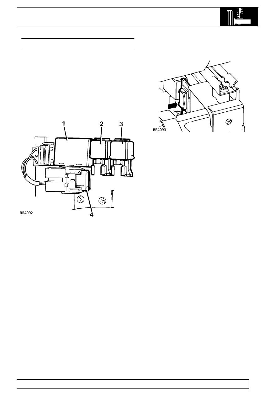
Relays, fuses
Power supply for the system consists of the following
components:
1. Delayed power turn off relay. This remains
powered up for 20 seconds after exiting vehicle
to allow self levelling.
2. Compressor relay, 4 pin.
3. Warning light relay, 5 pin.
4. 30 amp ’maxifuse’ for compressor power.
15 amp fuse in dash fusebox for ECU pin 1.
Disable switch
The disable switch is mounted on the RH runner
under the rear of the RH front seat. The switch has no
markings, in the DISABLE position the bottom of the
switch is pushed in. It is used to disable the system
when the vehicle is being delivered, or when working
on the system after depressurising. The switch
disables the system at speeds below 56 kph (35
mph).
Height sensors
Four potentiometer type height sensors signal vehicle
height information to the ECU. The potentiometers are
mounted on the chassis and activated by links to the
front radius arms and rear trailing links. In case of
height sensor failure the assembly must be replaced.
