
LOCATION OF COMPONENTS (70 - BRAKES - ABS)
- Make
- Land Rover
- Model
- Range Rover Classic
- Section
- DESCRIPTION AND OPERATION › LOCATION OF COMPONENTS
ABS
5
DESCRIPTION AND OPERATION
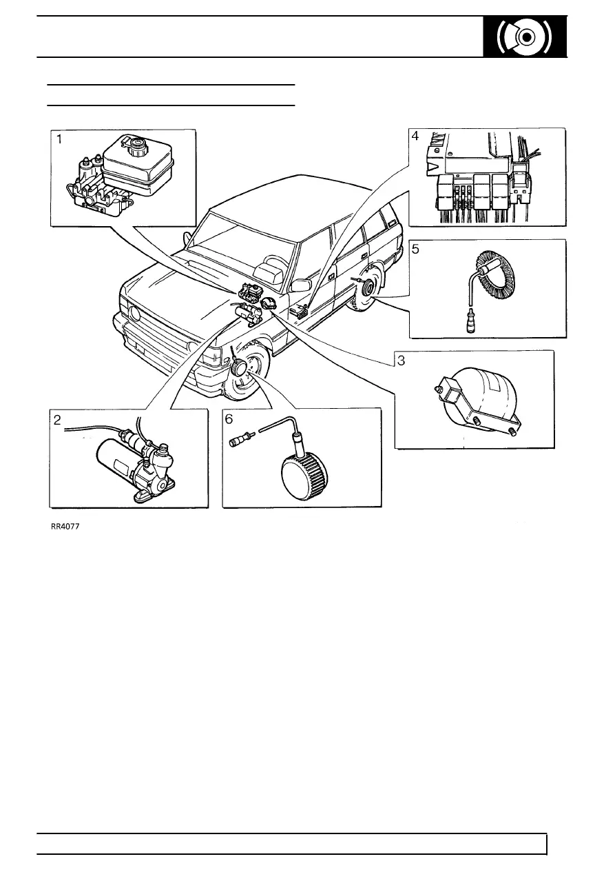
LOCATION OF COMPONENTS
Key to diagram (RR4077)
1. Hydraulic booster unit.
2. Power unit - hydraulic pump.
3. Accumulator.
4. Electronic control unit (ECU), relays and fuses.
5. Rear sensors/exciter rings.
6. Front sensors/exciter rings.
Electronic control unit - ECU
ABS operation is controlled by ECU located under left
hand front seat, and earthed to centre tunnel.
ECU is connected to ABS harness by a 35 way
connector.
The ECU is a non-serviceable item, it must be
replaced if failure occurs.
Sensors, exciter rings - 4 off
A sensor is mounted at each wheel, sensing a 60
tooth exciter ring. When vehicle is in motion inductive
sensors send signals to ECU. Front exciter ring is
fitted to outside diameter of constant velocity joint in
each front hub. Rear exciter ring is bolted to rear of
each brake disc bell.
Parts & tools for this job For Land Rover Range Rover
- TOOLOBD2 scanner with ABSSearch: OBD2 scanner ABS SRS
- TOOLDigital multimeterSearch: automotive digital multimeter
Links open Amazon search results in a new tab. As an Amazon Associate I earn from qualifying purchases.